Overview - Pistons And Connecting Rod
WARNING: This page is about a different variant/trim than selected.
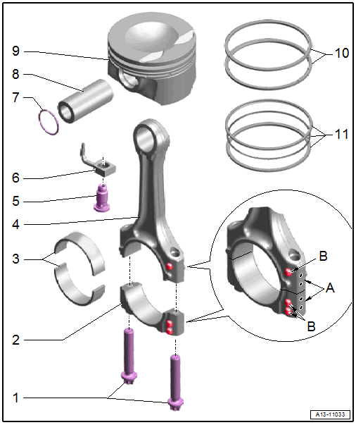
- Bolts
- 45 Nm + 90°
- Replace after removing
- Coat the threads and contact surfaces with engine oil
- Use old bolts for the radial clearance measurement
- Connecting Rod Bearing Cap
- Note the installation position
- Due to the separation procedure (cracking) of the connecting rod, the connecting rod bearing cap only fits in one position and only to the corresponding connecting rod.
- Use a color to mark the cylinder and connecting rod to which it belongs -A-
- Installation position: the locating tabs -B- face the belt pulley side
- Separating the new connecting rod. Refer to NEW CONNECTING ROD, SEPARATING .
- Bearing Shells
- Installation position. Refer to Fig 3.
- Allocation. Refer to Fig 2.
- Coat with engine oil before installing
- Radial play, measuring. Refer to CONNECTING RODS, CHECKING RADIAL CLEARANCE .
- Connecting Rod
- Always replace as a set
- Label the allocation of the cylinder to the connecting rod bearing cap -A-.
- Installation position: the locating tabs -B- face the belt pulley side
- Separating the new connecting rod. Refer to NEW CONNECTING ROD, SEPARATING .
- Radial play, measuring. Refer to CONNECTING RODS, CHECKING RADIAL CLEARANCE .
- Relief Valve
- 27 Nm
- Oil Spray Jet
- For piston cooling
- Installation position. Refer to Fig 7.
- Removing and Installing. Refer to OIL SPRAY JETS, REMOVING AND INSTALLING .
- Circlip
- Replace after removing
- Piston Pin
- Coat with engine oil before installing
- Piston
- Removing and Installing. Refer to PISTONS, REMOVING AND INSTALLING .
- Installation position: the arrow on piston face points toward belt pulley side.
- Mark which cylinder belongs to which
- Check piston and cylinder bore. Refer to PISTON AND CYLINDER BORE, CHECKING .
- Compression Rings
- Oil Scraping Ring
- Carefully remove and install the three-part oil scraping ring by hand
- Install the upper joint of the 3-part oil scraping ring 120° offset to the neighboring compression ring
- Piston ring gap is not measurable
- Height clearance cannot be measured
- Installation position. Refer to Fig 6.
- Allocation. Refer to Fig 4.
Bearing Shell - Allocation
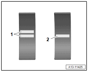
- Connecting Rod Bearing Cap Bearing Shell: Two White Stripes
- Connecting Rod Bearing Shell: One White Stripe
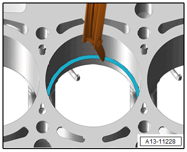
Bearing Shell - Installation Position
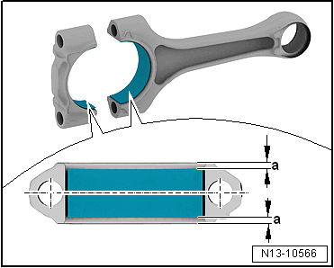
-- Place the bearing shells centrally into connecting rod and connecting rod bearing cap.
- Dimension -a- = dimension -a-.
Allocation and Piston Ring
 Courtesy of AUDI OF AMERICA, LLC
- Compression ring with bevel -A- on the inside top in the upper groove. >>TOP<< marking or lettering points upward.
- Compression ring with offset -B- on the outside bottom in the center groove. >>TOP<< marking or lettering points upward.
- Oil Scraping Ring.
Installing the Compression Ring
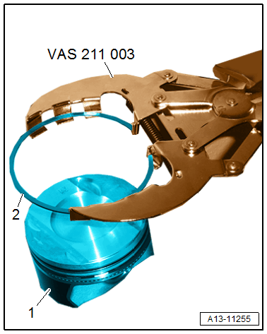
- >>TOP<< marking or lettering points upward.
- Only open the compression ring -2- using the : VAS211003 only until it can be pushed over the pistons -1-.
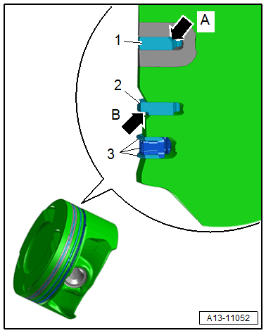
Installing the Oil Scraping Ring
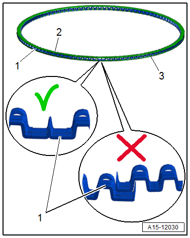
-- Pay attention to the spring installation position:
- The plunger of the plates -2 and 3- and the spring -1- must be offset 90° to each other.
- Install by hand.
Installation sequence:
-- 1. Insert the spring -1- in the groove.
-- 2. Insert the lower plate -3- in the groove.
-- 3. Insert the upper plate -2- in the groove.
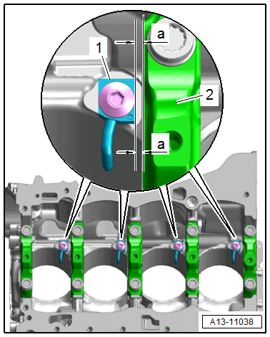
Oil Spray Jets - Installation Position
- The side surface of the oil spray jet -1- must be parallel to the neighboring crankshaft bearing -2-.
- Dimension -a- = dimension -a-.