97 Wire Harness Repairs And Documentation (GROUP 97, NO. 22-89)
Reference number: GROUP 97, NO. 22-89
Supersedes refnos: 2061976, 2061976/1, 2061976/2, 2061976/3, GROUP 97, NO. 21-78, GROUP 97, NO. 21-82
97 WIRE HARNESS REPAIRS AND DOCUMENTATION
TECHNICAL SERVICE BULLETIN
| AUDI: | 2018-2024 All Models |
| GROUP: | 97 - Electrical Wiring |
SERVICE INFORMATION
97 22 89 2061976/3 November 17, 2022. Supersedes Technical Service Bulletin Group 97 number 21-82 dated November 22, 2021, for reasons listed below.
| Model(s) | Year | VIN Range | Vehicle-Specific Equipment |
|---|---|---|---|
| All Audi vehicles | 2018 - 2024 | All | Not Applicable |
CONDITION
| Revision | Date | Purpose |
|---|---|---|
| 3 | - | Revised header (Added Models and Model Years) |
| 2 | 11/22/2021 | Revised header (Added Models) |
| 1 | 02/18/2021 | Initial publication |
Customer states:
- A warning or malfunction is present.
Workshop findings:
- A wiring issue is identified as a root cause.
TECHNICAL BACKGROUND
During service, a wiring issue is diagnosed as a root cause of failure. When reviewing warranty claims critical information describing the symptoms, findings, circuit affected and location of the damage is often unclear.
We are requesting your assistance in identifying and documenting wiring repairs. This helps identify common repairs and improve product designs.
PRODUCTION SOLUTION
Not applicable.
SERVICE
Once a wiring issue has been identified we ask for your cooperation in documenting the findings and taking photos of the damage found. Please retain the photos for at least 1 month after the claim is approved in case they are needed during warranty review.
For root causes relating to pins or coaxial connector ends:
- Retain approximately 10-20 mm of the original wire where space allows.
- Repair connection using VAS1978B.
For root causes relating to high resistance or a short circuit in the wiring:
- Overlays may be used for diagnosis.
- Retain the affected section of wire that was removed/faulty.
- Repair faulty sections of the wire using VAS1978B.
- Circuit affected.
- Pin identification of the main circuit affected.
- Circuit checks made including any resistance and/or voltage values of the affected circuit.
- Location of where the damaged pin or circuit is found.
- Any other relevant details to support and describe the findings.
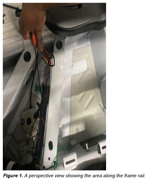
Example: Flexray circuit measured .6 ohm to ground with no components connected to the circuit. Short circuit to ground present on the green FlexRay wire between J743 Dual Clutch T23/1 and J533 Data Bus on Board Diagnostic Interface T54/27. Located damaged wire section underneath the driver seat along the frame rail.
Photos are needed for accurate location and findings:
- 1 perspective view - Shows the general area and provides a reference of the surrounding area (Figure 1).
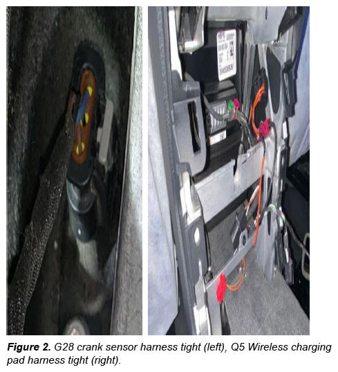
- 1 original routing - Taken before the area of concern is disturbed (Figure 2).
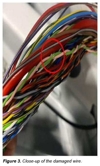
- 1 close up - clearly focused and showing the damaged circuit (Figure 3).
Photos should:
- Have a date stamp and VIN reference.
- Be taken in focus and with sufficient light.
Perspective view:
Using the description in the example above, the root cause can be clearly identified in Figure 1.
Routing concerns:
When a harness routing is determined to be the root cause, a photo should be taken to show how the harness was routed in its normal state (Figure 2).
Close-up:
Using the description in the example above, the damage to the FlexRay wire is clearly visible in Figure 3.
No TAC case: Please retain photos for at least 1 month after claim approval in case they are requested during claim review.
TAC case present: If a case is made before or after a wiring issue is identified, please update the TAC case with all information described above.
Tip: For additional information on circuit diagnosis, identifying circuits and making repairs, please visit the Audi academy website, Accessaudi >> App links >> Academy site CRC >> videos >> Technical >> Electrical, networking and vehicle lighting.
More information is included in Self-Study Programs (SSP):
- 973003 - How to Read Wiring Diagrams, Symbols, Layout, and Navigation.
- 971003 - Wiring Harness Inspection and Repair.
WARRANTY
When claiming wire repairs often times PID 9709 is used as a default PID. Using the correct PID helps to differentiate which harness is affected.
The table below lists examples of PID's to help claim repairs in specific locations. Please see the damage code catalog in Elsa for a more comprehensive list, Elsa >> damage code catalog >> Electrical >> 97 Wiring.
| PID | Description | Notes |
|---|---|---|
| 9709 | Central Wiring Harness | For main body harness only. Not for sub-harness' that are replaceable separately. Ex: door, bumper, or engine harness. |
| 9713 | Engine compartment wiring harness | Any repair made to the harness sections in the engine bay NOT connected to the main body harness. Claim notes should specify a location. |
| 9732 | Door harness | Use for any door. Claim notes should state which door. |
| 9757 | Seat harness | Use for any location. Claim notes should specify the location. |
| 9779 | Roof wiring harness | Any repairs made to harness sections in the roof. Claim notes should specify a location. |
| 9759 | Bumper harness | Use for front or rear. Claim notes should specify the location. |
| 9781 | Transmission wiring harness | Any repair made to the harness that is separate from the main body harness and connects to the transmission. |
REQUIRED PARTS AND TOOLS
| Tool Number | Tool Description |
|---|---|
| VAS 1978B | Wiring harness repair set |
| VAS 6160/VAS 6150 | VAS tester with the current version of ODIS (Windows 10) |
ADDITIONAL INFORMATION
More information on this system can be found in the following resources:
- Audi academy: Accessaudi >> App links >> Academy site CRC >> videos >> Technical >> Electrical, networking and vehicle lighting.
- Elsa: damage code catalog >> Electrical >> 97 Wiring.
- SSP: 973003 How to Read Wiring Diagrams, Symbols, Layout, and Navigation.
- SSP: 971003 Wiring Harness Inspection and Repair.
All part and service references provided in this TSB (2061976 ) are subject to change and/or removal. Always check with your Parts Department and/or ETKA for the latest information and parts bulletins. Please check the Repair Manual for fasteners, bolts, nuts, and screws that require replacement during the repair.
©2022 Audi of America, Inc. All rights reserved. The information contained in this document is based on the latest information available at the time of printing and is subject to the copyright and other intellectual property rights of Audi of America, Inc., its affiliated companies, and its licensors. All rights are reserved to make changes at any time without notice. No part of this document may be reproduced, stored in a retrieval system, or transmitted in any form or by any means, electronic, mechanical, photocopying, recording, or otherwise, nor may these materials be modified or reposted to other sites, without the prior expressed written permission of the publisher.