50 Creaking Noises Heard When Body Twists During Braking Or Steering Maneuvers (GROUP 50, NO. 24-15)
Reference number: GROUP 50, NO. 24-15
Supersedes refnos: 2062633/1, 2062633/2, 2062633/3, GROUP 50, NO. 21-06, GROUP 50, NO. 23-12
50 CREAKING NOISES HEARD WHEN BODY TWISTS DURING BRAKING OR STEERING MANEUVERS
TECHNICAL SERVICE BULLETIN
| AUDI: | 2017-2024 A4, and A4 allroad; 2018-2024 S4, A5, A5 Cabriolet, A5 Sportback, S5, S5 Cabriolet, and S5 Sportback; 2018-2019, 2021-2024 RS 5; 2019, 2021-2024 RS 5 Sportback; 2021-2025 Q5, Q5 e quattro, Q5 Sportback, SQ5, and SQ5 Sportback |
| GROUP: | 50 - Body - Front Section, Dimensions |
SERVICE INFORMATION
50 24 15 2062633/3 November 25, 2024. Supersedes Technical Service Bulletin Group 50 number 23-12 dated March 17, 2023, for reasons listed below.
| Model(s) | Year | VIN Range | Vehicle-Specific Equipment |
|---|---|---|---|
| A4, and A4 allroad | 2017 - 2024 | All | Not Applicable |
| S4, A5, A5 Cabriolet, A5 Sportback, S5, S5 Cabriolet, and S5 Sportback | 2018 - 2024 | ||
| RS 5 | 2018 - 2019 2021 - 2024 |
||
| RS 5 Sportback | 2019 2021 - 2024 |
||
| Q5, Q5 e quattro, Q5 Sportback, SQ5, and SQ5 Sportback | 2021 - 2025 |
CONDITION
| Revision | Date | Purpose |
|---|---|---|
| 3 | - | Revised header (added models) Revised Service (Added photo/video documentation requirement) Revised Warranty (Updated Labor Operations) Revised Required Parts and Tools (Change to material) |
| 2 | 03/17/2023 | Revised header (Model Year 2023 added) Revised Warranty (SRT change) Revised Required Parts and Tools (Change in cavity wax material) |
| 1 | 03/20/2021 | Initial publication |
Customer states:
- A creaking type noise is heard in the floor area.
- The noise can be generated during strong braking or steering maneuvers where the vehicle body is twisted.
Workshop findings:
- Diagnosis locates the source of the noise from the floor area specifically radiating from the footwell to the area under the seat.
TECHNICAL BACKGROUND
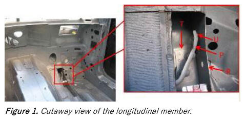
During a cornering or hard braking maneuver, the longitudinal member reinforcement plate 'P' over the threaded console 'T' can make contact at point 'U' (Figure 1).
PRODUCTION SOLUTION
There has been an improvement in the construction of the longitudinal member assembly.
SERVICE
- Duplicate the noise on a test drive preferably with the customer so that the conditions under which this symptom presents are clearly identified. Also determine from which side of the vehicle the noise originates. If this noise is duplicated on the test drive confirmation that the source of the noise is from the longitudinal member and that the repair described in this TSB will be effective can be achieved as follows.
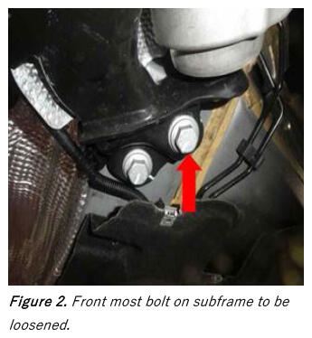
- Begin your diagnosis by loosening the frontmost bolt on the subframe mounting as indicated in Figure 2. The bolt only needs to be loosened several turns but not removed.NOTE: As specified in the repair manual, it is necessary to replace all loosened subframe bolts at the conclusion of the entire repair.
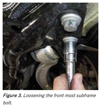
- In many cases an audible 'cracking' noise can be heard in the course of loosening and tightening the subframe bolt (Figure 3).
- Test drive the vehicle.
- If there is no change or elimination of the noise achieved during this diagnostic step, the repair in this TSB will not be effective and diagnosis must continue outside the scope of this repair procedure.
- If the noise characteristics do, in fact, change or if the noise is eliminated proceed as follows.
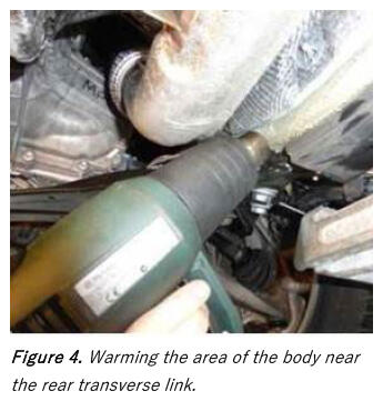
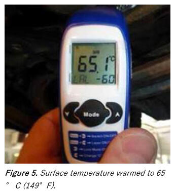
- Duplication of this noise is difficult when the vehicle is cold. If you suspect that the cold is preventing duplication of this symptom warm up the longitudinal member/body in the area of the rear transverse link bolted connection with a hot air blower set for an outlet temp of approximately 550°C (1022°F) (Figure 4).
- Warm the surface to approximately 65°C (149°F) (Figure 5).
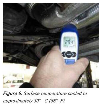
- Allow the surface temperature to cool to approximately 30°C (86°F) then test drive the vehicle again (Figure 6).
- Merely lowering the vehicle from the hoist can immediately elicit the noise symptom after this warming process.
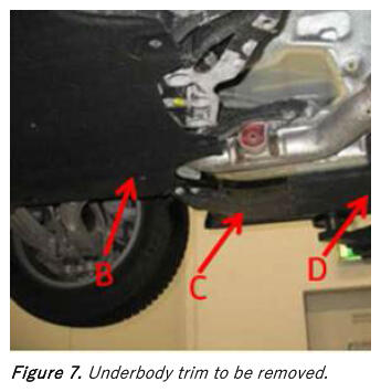
- With the symptom confirmed, remove the front middle underbody trim 'B', front underbody trim 'C', and the underbody trim 'D' (Figure 7).
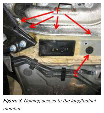
- In order to provide appropriate access to the affected area inside the longitudinal member begin by unscrewing the four sheet nut fasteners 'F' for the heat shield from their studs.
Bend the heat shield slightly away from the longitudinal member (Figure 8).
Remove grommet 'E'.
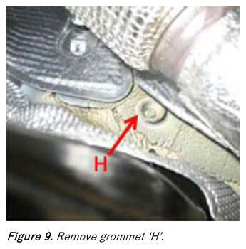
- Remove grommet 'H' from the longitudinal member (Figure 9).
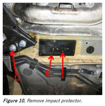
- Because bolt 'G' was loosened in the diagnosis process it must be replaced. Replace bolt 'G' using the installation and tightening procedure in ElsaPro.
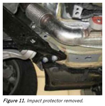
Remove the impact protector 'K'. Pry out clip 'I' from the impact protector and remove it from the longitudinal member (Figures 10 - 11).
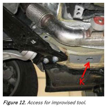
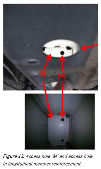
- By shining a flashlight through the opening 'K' from the now removed impact protector you can see the upper round hole 'M' (Figure 12) in the longitudinal member reinforcement plate 'N' (Figure 13) when viewed through hole 'L' (hole from grommet 'E' from Figure 8).
- Figure 13 shows the view through hole 'L' when illuminated through hole 'K' (Figure 12). This is the path through which you will insert an improvised chisel.
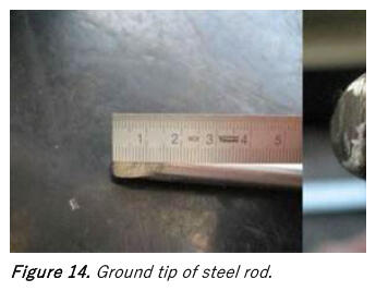
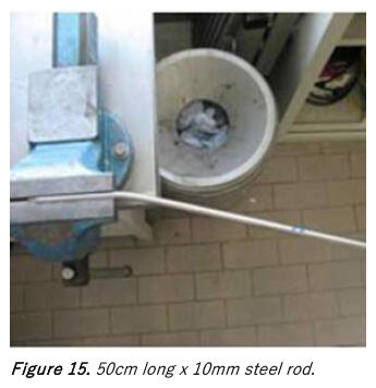
- An improvised tool for this modification will be necessary. Begin fabricating this tool by obtaining a steel rod 10mm in diameter and 50cm long (Figure 14). Grind the tip of one end of the rod into a chisel shape. The length of the grind should be 15mm +/-3mm on each side as shown in Figure 14.
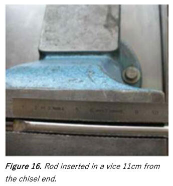
- Mount one end of the rod into a vice 11cm deep with the chisel shape parallel to the ground (Figure 15).
- A bend will be created 11cm deep from the chisel end (Figure 16).
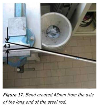
- Bend the steel bar at the 11cm apex until a distance of 43 mm +/- 3 mm is created between the axis of the longer end of the rod and the axis of the shorter end of the rod at its tip (Figure 17).
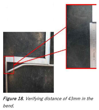
- Measure and verify this distance (Figure 18).
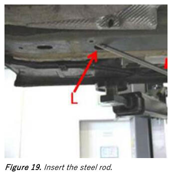
- Insert the chisel end of the steel rod 'A' into the body opening 'L' in the longitudinal member (Figure 19).
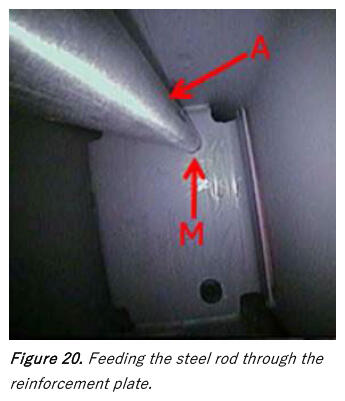
- Now feed steel rod 'A' through hole 'M' (upper hole) in the reinforcement plate (Figure 20).
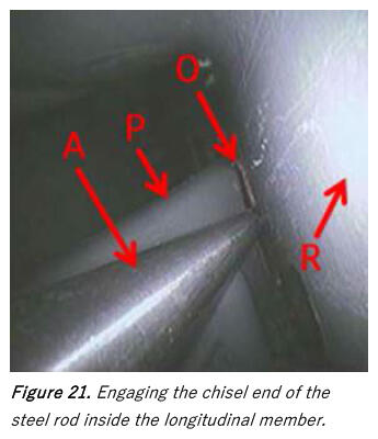
- The chisel end of the steel rod is to be fed far enough to engage the front reinforcement plate 'P' at point 'O' such that it is lodged into the gap between reinforcement plate 'P' and the wall of the longitudinal member 'R' (Figure 21).
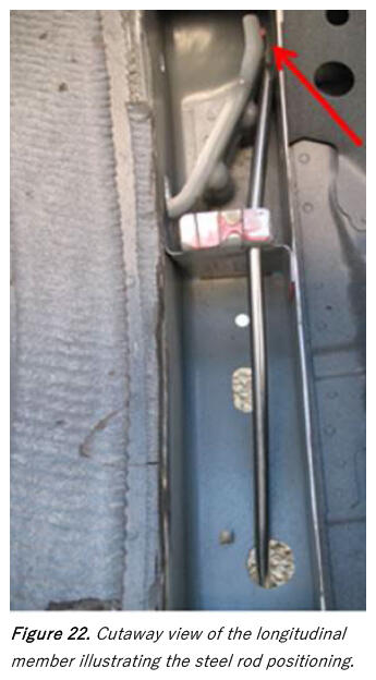
- If the steel rod bend angle and chisel point orientation are created as described the tool will reach the appropriate point of contact when it is guided into the holes in the longitudinal member as described (Figure 22).
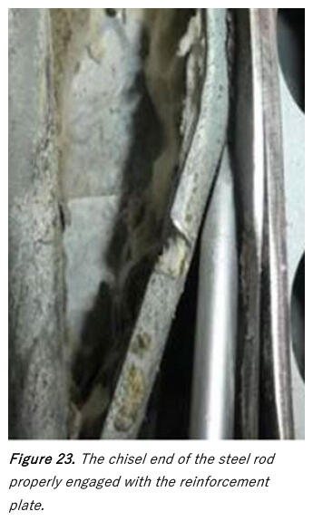
- The chisel end of the steel rod must be inserted as shown in Figure 23 with the wedge engaged consistent with the space formed by the longitudinal member support to the longitudinal member housing.
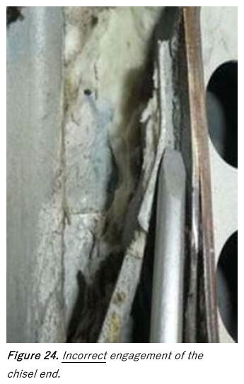
- Figure 24 shows an incorrect
engagement of the chisel end.
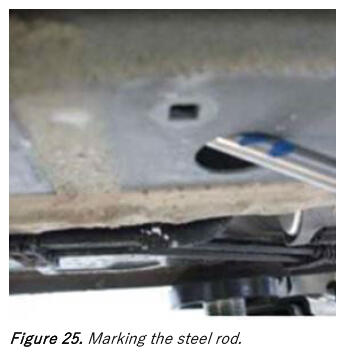
- Using a marker mark the point at which the steel rod makes contact with the longitudinal member. Then make a mark 10mm - 15mm rearward of that contact point on the steel rod (Figure 25).
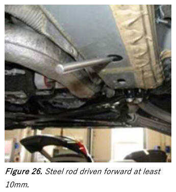
- Using a hammer drive the steel rod a distance of 10 mm. Then pull the bending tool out of the longitudinal member again (Figure 26).
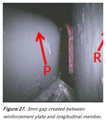
- As a result, a distance of approximately 3 mm is created between reinforcement plate 'P' and the longitudinal member 'R'. Separating this point of contact eliminates the noise generation (Figure 27).
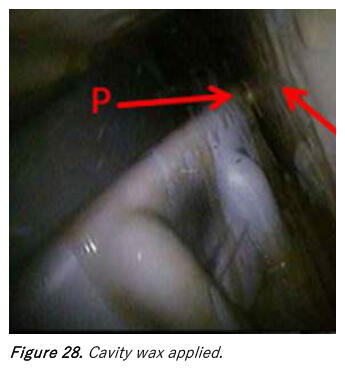
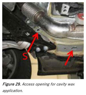
- All points that were contacted and/or struck are likely have had their corrosion protective layer compromised. Because of this thoroughly coat all areas with cavity way (Figure 28).
- Cavity wax can be applied through the openings shown in figure 28. The separation point in the longitudinal member can be accessed through hole 'S' (Figure 29).
Reassemble the vehicle as per the repair manual.
- Perform a final test drive to confirm elimination of the noise by duplicating the driving conditions specified by the customer. Ensure that the noise has been eliminated to the customer's satisfaction by driving with the customer at the time they take possession of the vehicle after repair.
- When billing, please always attach a photo that clearly shows the complaint to DOC-IT. To ensure a reference to the vehicle, the photo must include the VIN number and date. The photo must not be edited. The photo should be in focus and taken with sufficient light. A high resolution is not necessary. If appropriate, please mark the location of the problem so that parts analysis has a clear reference to the complaint. Please ensue that the photo documentation does not show any persons and/or face, license plates, or customer data.
WARRANTY
| Claim Type: |
|
||
| Service Number: | 5079 | ||
| Damage Code: | 0010 | ||
| Labor Operations: | Check longitudinal member | 5079 0199 | 40 TU |
| Modify longitudinal member | 5079 4199 | 100 TU | |
| Cavity sealing | 5101 7501 | See SRT with associated operations | |
| 3 Road tests prior to the service procedure | 0121 0199 | 30 TU | |
| Road test after the service procedure | 0121 0004 | 10 TU | |
| Claim Comment: | As per TSB 2062633/3 | ||
All warranty claims submitted for payment must be in accordance with the Audi Warranty Policies and Procedures Manual . Claims are subject to review or audit by Audi Warranty.
REQUIRED PARTS AND TOOLS
Always check with your Parts Department and/or ETKA for the latest information and parts bulletins.
| Part Number | Part Description | Quantity |
|---|---|---|
| D 329215M2 | Cavity preservative | 0.25 |
| See ETKA | Bolt hex head | 02 per side |
ADDITIONAL INFORMATION
All parts and service references provided in this TSB (2062633) are subject to change and/or removal.
©2024 Audi of America, Inc. All rights reserved. The information contained in this document is based on the latest information available at the time of printing and is subject to the copyright and other intellectual property rights of Audi of America, Inc., its affiliated companies, and its licensors. All rights are reserved to make changes at any time without notice. No part of this document may be reproduced, stored in a retrieval system, or transmitted in any form or by any means, electronic, mechanical, photocopying, recording, or otherwise, nor may these materials be modified or reposted to other sites without the prior expressed written permission of the publisher.