AWD Vehicles
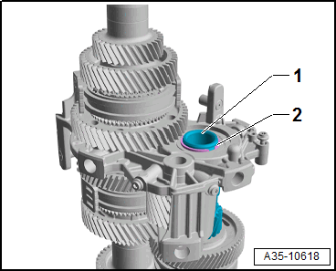
-- Remove the circlip -arrow-.
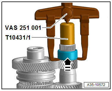
-- Remove the bearing inner race -Item 25- or -Item 30- -arrow- using the Two-Arm Puller (Kukko 20/10) :VAS 251 001 and Seal Installer - Shaft Seal :T10431/1 .
Vehicles without self-locking center differential
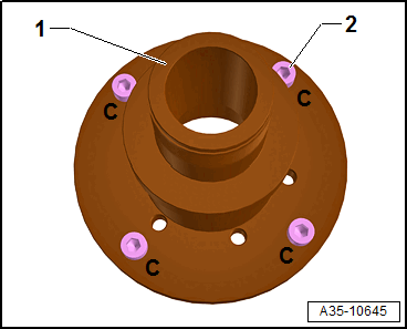
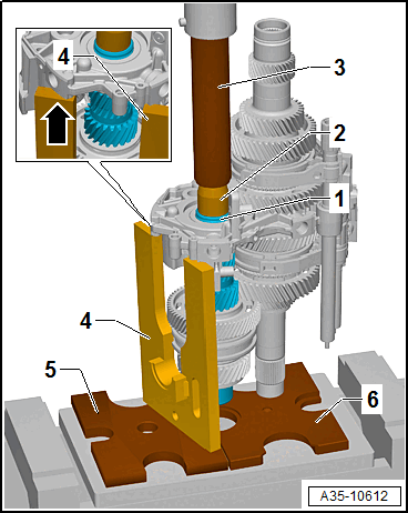
-- Install the four bolts (M8 x 30) -2- in the threaded holes marked with "C" from the Extracting Tool - Adapters :T40413/7 -1-.
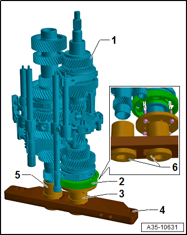
-- Bolt the Extracting Tool - Adapter :T40413/7 with the Gearbox Assembly Tool :T40213A .
-- Tighten the Gearbox Assembly Tool :T40213A in the vise or on the Gearbox Support :T40206 .
-- Insert the gear set -1- in the Assembly Tool.
- The gear set is secured with the Retaining Strap :T40155 and Engine/Gearbox Support Shackle (2 pc.) :10-222A/12 on the Workshop Crane :VAS 6100 .
- The bolts from the Extracting Tool - Adapter :T40413/7 -3- must engage in the holes in the gear assembly from the 7th gear -2-.
3 - Extracting Tool - Adapter :T40413/7
4 - Gearbox Assembly Tool :T40213A
5 - Extracting Tool - Adapter :T40413/8
6 - Extracting Tool - Nut :T40213/3
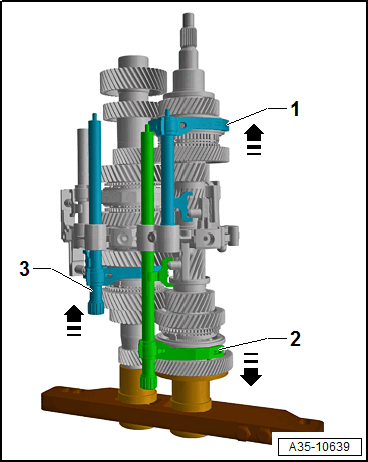
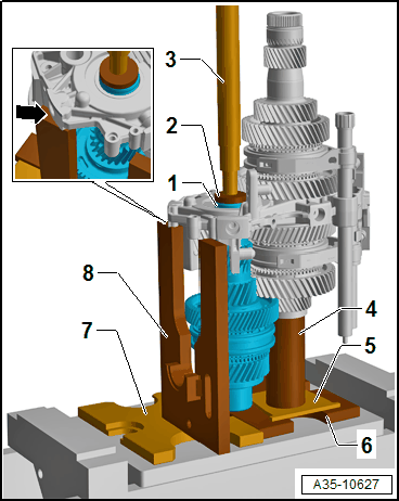
-- Switch the Gearshift Rail/Shift Fork for 4th and 6th Gear -1-, Gearshift Rail/Shift Fork for 5th and 7th Gear -2- and Gearshift Rail/Shift Fork for 1st and 3rd Gear -3- in the -direction of the arrows-.
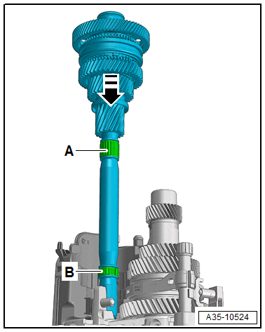
-- Warm the bolt -arrow- to approximately 100 °C (212 °F).
Tip:
- The bolt from the output shaft has a very high loosening torque.
-- Remove the bolt -arrow- with the Socket - Xzn 18mm :T10162A -1-.
If when warning the bolt the oil pipe -2- in the output shaft is damaged it must be replaced.
-- Drive out the oil pipe -2- using the Valve Guide/Clutch Release Push Rod Seal Drift :10-206 -1- from the output shaft in the -direction of the arrow-.
-- Drive in the new oil pipe on the opposite side again.
-- Then shift all gears into the transmission neutral position.
Continuation for all vehicles
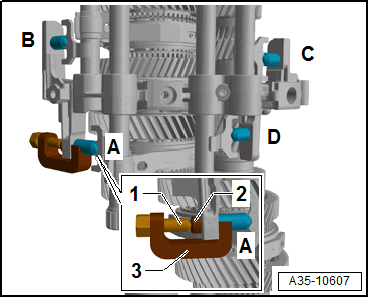
-- Remove the bolt -arrow- and remove the shift forks for 4/6 gear and 5/7 gear together.
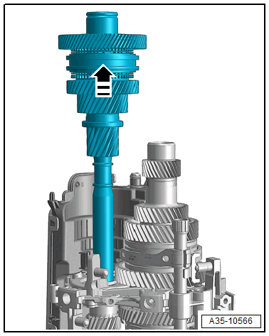
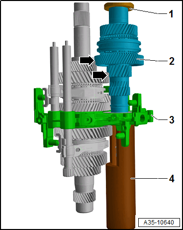
-- Remove the input shaft 1 from the gear set.
Damage to input shaft 1
- When removing the input shaft 1, the 7th gear wheel may already be loosened and can fall.
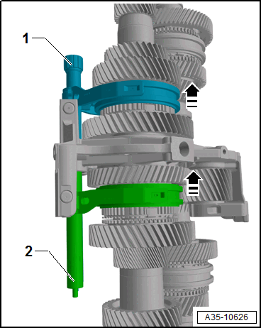
-- Shift fork the gearshift rail/shift fork for 1st and 3rd gear -1- and gearshift rail/shift fork for 2nd gear and reverse gear -2- upward in the -direction of the arrow-.
Vehicles with self-locking center differential
-- Remove the circlip -1- from the outer output shaft -2-.
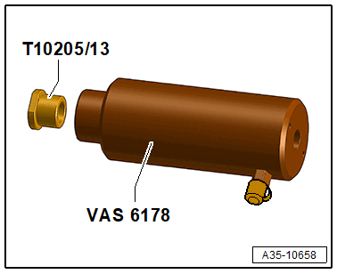
Screw in the Thrust Piece :T10205/13 in the Hydraulic Cylinder :VAS 6178 .
Press on the 4th gear 1, vehicles with self-locking center differential
 Courtesy of AUDI OF AMERICA, LLC
2 - Press Piece - Multiple Use :30-11
3 - Press Piece - 31.5mm :VW418A
4 - Extracting Tool - Screwdriver Bit :T40413/2
5 - Hydraulic Press :VAS 6178
6 - Extracting Tool - Puller :T40413/1
Vehicles without self-locking center differential
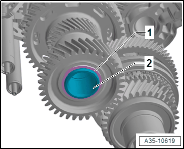
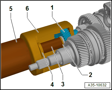
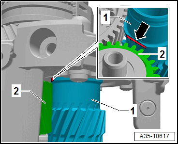
Drive Wheel for spur gear unit 1 and drive wheel roller bearing inner race 2.
 Courtesy of AUDI OF AMERICA, LLC
3 - Press Piece - Multiple Use :VW426
4 - Extracting Tool - Screwdriver Bit :T40413/2
5 - Extracting Tool - Puller :T40413/1
6 - Hydraulic Press :VAS 6178
-- Remove the spacer sleeve -Item 4-.
Press on the 4th gear 1, vehicles without self-locking center differential
 Courtesy of AUDI OF AMERICA, LLC
2 - Extracting Tool - Screwdriver Bit :T40413/2
3 - Hydraulic Press :VAS 6178
4 - Extracting Tool - Puller :T40413/1
Continuation for all vehicles
-- Remove the circlip -2- for the drive axle 2 -1-.
Align the drive axle 2 1
Risk of destroying the gears, shaft and bearing bracket.
- To press out the input shaft 2, align as follows.
- The bevel -arrow- of the drive axle 2 -1- must be located on the side of the intermediate sprocket for the reverse gear -2-.
Press out the drive axle 2 1, vehicles without self-locking center differential
 Courtesy of AUDI OF AMERICA, LLC
2 - Bearing Installer - Multiple Use :32-111
3 - Press Piece - Rod :VW407
4 - Bearing Installer - Bearing Press Plate :T10084A
5 - Press Plate :VW401
6 - Press Plate :VW402
- To press on the drive axle 2 have a second technician help.
- The bearing bracket must be positioned on the Bearing Installer - Bearing Press Plate :T10084A -arrow-.
Press out the drive axle 2 1, vehicles with self-locking center differential
 Courtesy of AUDI OF AMERICA, LLC
2 - Press Piece - Multiple Use :40-105
3 - Press Piece - Rod :VW408A
4 - Press Piece - Multiple Use :VW519
5 - Exhaust Pipe Wedge Set :3140A/1
6 - Press Plate :VW402
7 - Press Plate :VW401
8 - Bearing Installer - Bearing Press Plate :T10084A
- To press on the drive axle 2 have a second technician help.
- The bearing bracket must be positioned on the Bearing Installer - Bearing Press Plate :T10084A -arrow-.
Continuation for all vehicles
Depending on the servicing in the next work procedure:
- Input Shaft 2, Disassembling and Assembling. Refer to INPUT SHAFT 2, DISASSEMBLING AND ASSEMBLING .
- Input Shaft 1, Disassembling and Assembling. Refer to INPUT SHAFT 1, DISASSEMBLING AND ASSEMBLING .
- Output Shaft, Disassembling and Assembling. Refer to OUTPUT SHAFT, DISASSEMBLING AND ASSEMBLING .
- Vehicles with self-locking center differential: inner output shaft disassembling and assembling. Refer to INNER OUTPUT SHAFT, DISASSEMBLING AND ASSEMBLING, ONLY VEHICLES WITH SELF-LOCKING CENTER DIFFERENTIAL .
Assembling
Insert the input shaft 2 2 in the bearing bracket
- Warm up the output shaft bearing -1- using the Hot Air Blower.
- The bevel -arrow- of the output shaft 2 must be located on the side of the intermediate sprocket for the reverse gear -3-.
Press in the input shaft 2 2 in the bearing bracket 3
- When pressing in the input shaft 2 pay attention to the splines -arrows-.
1 - Press Piece - Multiple Use :VW412
4 - Extracting Tool - Sleeve :T40413/10
-- Determine and insert the thickest circlip -2- that can still be inserted for the drive axle 2 -1-.
The following circlips are available. Refer to the => Parts Information for the part number.
| Circlip thickness (mm) | ||
|---|---|---|
| 2.41 | 2.49 | 2.57 |
| 2.45 | 2.53 | |
4th Gear 1, Installing
3 - Bearing Installer - Differential Bearing :40-21
- Warm the 4th gear -1- using the Inductive Heater :VAS 6414 to 120 °C (248 °F).
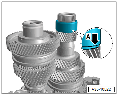
- When pressing on the splines -arrow- pay attention to the 4th gear -1- and the gear assembly for the 4th gear -2-.
- Vehicles with self-locking center differential: insert the circlip -Item 9-
Vehicles without self-locking center differential
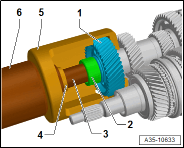
Drive wheel for spur gear unit 2, pressing on
3 - Bearing Installer - Differential Bearing :40-21
- Position the spacer sleeve -1- beforehand.
- Warm the drive wheel for spur gear unit -2- to 120 °C (248 °F) using the Inductive Heater :VAS 6414 .
- The groove on the drive wheel of the spur gear unit points to the Bearing Installer - Differential Bearing :40-21 .
Press on the output shaft roller bearing inner race 1
2 - Press Piece - Trailing Arm :2010
- Warm the output shaft roller bearing inner race -1- using the Inductive Heater :VAS 6414 to 120 °C (248 °F).
- Installation position: the lettering on the bearing -1- (thicker wall thickness) points to the Press Piece - Trailing Arm :2010 -2-.
Continuation for all vehicles
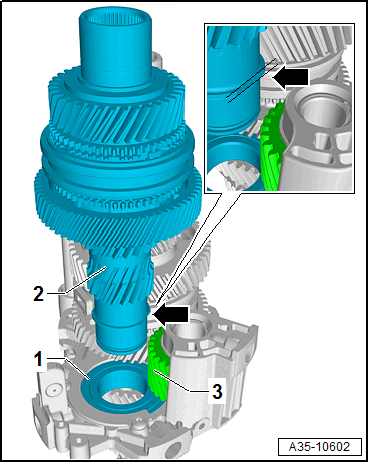
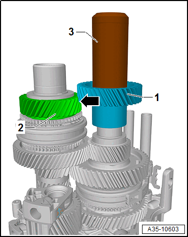
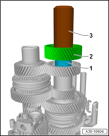
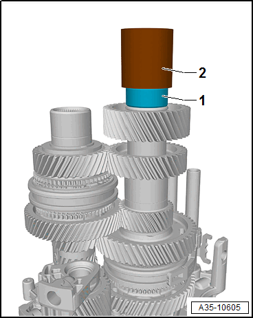
-- Carefully guide the input shaft 1 into the gear set -arrow-. While doing so, make sure the needle bearings -A and B- are installed correctly.
-- Position the shift forks and secure with the bolt -arrow-.
The following procedure is only necessary after disassembling the output shaft.
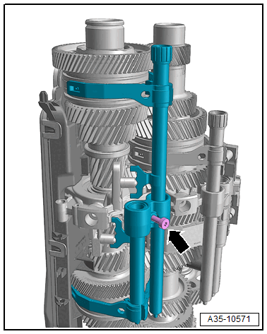
-- Press in the locking sleeve for the gearshift rail/shift fork 1st and 3rd gear -A- and the locking sleeve for the gearshift rail/shift fork 2nd and reverse gear -B-. Refer to Figure.
Vehicles without self-locking center differential
-- Install the four bolts (M8 x 30) -2- in the threaded holes marked with "C" from the Extracting Tool - Adapters :T40413/7 -1-.
-- Bolt the Extracting Tool - Adapter :T40413/7 with the Gearbox Assembly Tool :T40213A .
-- Tighten the Gearbox Assembly Tool :T40213A in the vise or on the Gearbox Support :T40206 .
-- Insert the gear set -1- in the Assembly Tool.
- The bolts from the Extracting Tool - Adapter :T40413/7 -3- must engage in the holes in the gear assembly from the 7th gear -2-.
3 - Extracting Tool - Adapter :T40413/7
4 - Gearbox Assembly Tool :T40213A
5 - Extracting Tool - Adapter :T40413/8
6 - Extracting Tool - Nut :T40213/3
-- Switch the Gearshift Rail/Shift Fork for 4th and 6th Gear -1-, Gearshift Rail/Shift Fork for 5th and 7th Gear -2- and Gearshift Rail/Shift Fork for 1st and 3rd Gear -3- in the -direction of the arrows-.
-- Clean the internal threads of the output shaft with a thread tap.
-- Install the new bolt -arrow- using the Socket - Xzn 18mm :T10162A -1- and tighten.
-- Then shift all gears into the transmission neutral position.
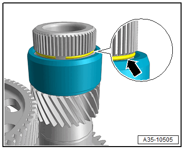
-- Warm the bearing inner race -Item 25- or -Item 30- with a Inductive Heater :VAS 6414 and push with the shoulder downward -arrow A- all the way.
-- Install the circlip -arrow-.
-- Install the oil pan -Item 5-.
-- Install the gear set. Refer to TRANSMISSION, DISASSEMBLING AND ASSEMBLING .
Tightening Specifications