Refrigerant Circuit with Expansion Valve, Receiver/Dryer and Second Evaporator
This main wiring diagram shows a refrigerant circuit with expansion valve, receiver/dryer and second evaporator (optional equipment on certain vehicles).
On vehicles with an expansion valve and receiver/dryer, the expansion valve is removed and replaced by an adapter. Depending on the vehicle, the receiver/dryer must also be removed and line connections to fluid reservoir be connected to each other by two adapters and a charge hose.
On a vehicle with only one evaporator, components from item "16" are not present or are not needed.
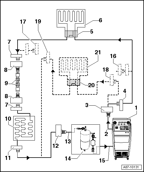
- A/C Service Station
- With electronics and a flushing program, A/C Service Station With Flushing Device. Refer to Parts Information (Tools; Special Tools and Equipment: A/C and Heating).
- If an A/C service station without a flushing program is used, the procedure must be performed manually (evacuate, flush three times with at least 4 kg refrigerant each and extract refrigerant again, evacuate).
- A/C Service Station Refrigerant Hose
- From the high pressure side of the A/C service station (mostly colored red) to the connection for the low pressure side of the A/C compressor on the refrigerant circuit (larger diameter).
- Adapter to Connection for Low Pressure Side on Refrigerant Circuit
- There are different versions depending on the vehicle. Refer to ADAPTER FOR ASSEMBLING FLUSHING CIRCUIT .
- From the Refrigerant Circuits Adapter Set 1 :VAS6338/1
- Low Pressure Side Connection on Refrigerant Circuit
- There are different versions depending on the vehicle. Refer to ADAPTER FOR ASSEMBLING FLUSHING CIRCUIT .
- Adapter for Removed Expansion Valve
- There are different versions depending on the vehicle. Refer to ADAPTER FOR ASSEMBLING FLUSHING CIRCUIT .
- From the Refrigerant Circuits Adapter Set 1 :VAS6338/1
- Evaporator
- Connection to Receiver/Dryer
- There are different versions depending on the vehicle. Refer to ADAPTER FOR ASSEMBLING FLUSHING CIRCUIT .
- Not present on vehicles with a dryer cartridge in the receiver/dryer on the condenser or with a receiver/dryer installed in the condenser. Refer to Refrigerant Circuit .
- Adapter for Bridging Removed Receiver/Dryer
- Not required for all vehicles.
- There are different versions depending on the vehicle. Refer to ADAPTER FOR ASSEMBLING FLUSHING CIRCUIT .
- From the Refrigerant Circuits Adapter Set 1 :VAS6338/1
- Refrigerant Charging Hose. Refer to ADAPTER FOR ASSEMBLING FLUSHING CIRCUIT .
- For example, Hose :VAS6338/31 (from the Refrigerant Circuits Adapter Set 1 :VAS6338/1 )
- Condenser
- If a receiver/dryer with dryer cartridge is installed on the condenser, the dryer cartridge must be removed (reseal the receiver/dryer at or in the condenser after removing). Refer to Refrigerant Circuit .
- If the receiver/dryer is attached directly to the condenser, the receiver/dryer must be removed and replaced only after flushing. Refer to Refrigerant Circuit
.NOTE:
On certain vehicles the receiver/dryer is integrated inside the condenser and the dryer cartridge cannot be replaced separately and is not available as a single part. In this case, replace the condenser with the receiver/dryer / dryer cartridge after flushing on these vehicles. Refer to Refrigerant Circuit and the Parts Information.
- High Pressure Side Connection on Refrigerant Circuit
- There are different versions depending on the vehicle. Refer to ADAPTER FOR ASSEMBLING FLUSHING CIRCUIT .
- Adapter to Connection for High Pressure Side on Refrigerant Circuit
- There are different versions depending on the vehicle. Refer to ADAPTER FOR ASSEMBLING FLUSHING CIRCUIT .
- From the Refrigerant Circuits Adapter Set 1 :VAS6338/1
- Charging Hose for Refrigerant Circuit Flushing Device
- From the connection to the high pressure side of the A/C compressor on the refrigerant circuit (smaller diameter) to the input of the refrigerant circuit flushing device.
- Refrigerant Circuit Flushing Device
- There are different versions of the Refrigerant Circuit Flushing Device. Refer to the Parts Information (Tools; Special Tools and Equipment: A/C and Heating).
- With filter, viewing glass, safety valve, heater, refrigerant reservoir, etc. (depending on version).
- Depending on the construction of the A/C service station and of refrigerant circuit flushing device, a check-valve may be installed at output of refrigerant circuit flushing device (to guarantee correct direction of refrigerant flow during flushing).
- Depending on the design of the refrigerant circuit flushing device, a connection for a refrigerant circuit service coupling may be located at the outlet (and possibly also at the inlet) of the flushing device (instead of a 5/8-18 UNF external thread). If a service connection with a valve is installed on the outlet of the flushing device, this valve must be all the way open when the service coupling is attached (a partially opened valve creates a constriction). If there is a connection for a service coupling on the inlet of the flushing device, the inlet must be modified so that the refrigerant hose coming from the vehicle can be directly connected (a service coupling and a valve in the flushing device inlet create a constriction that impedes the flow of refrigerant from the vehicle to the flushing device and thus the flushing procedure).CAUTION:
Risk of icing over the output of the flushing device via the installed valve which is not correctly opened.
- A partially opened valve installed in this connection creates a constriction that impairs the flow of refrigerant in the flushing device and can ice over due to severe cooling.
- If there is a service connection with a valve on the outlet of the flushing device, this valve must be all the way open during the flushing procedure.
- If there is too strong of cooling (icing over) at the outlet of the flushing device during the flushing procedure, stop the flushing procedure and evacuate the refrigerant from the flushing device and the vehicle via the high and low pressure side. Check the valve in the outlet of the flushing device and service it if necessary.
Risk of icing on the input of the flushing device due to a constriction which is created via a service coupling and in a service connection installed valve.
- Remove the service connection installed on this connection, and connect the service hose that comes from the vehicle directly (without constriction) to the flushing device, possibly using a necessary adapter (depending on the inlet thread of the flushing device).
- A/C Service Station Refrigerant Hose
- From the A/C service station low pressure side (mostly blue) to the outlet of the refrigerant circuit flushing device.
- Adapter for Sealing Outlet to Second Evaporator
- Only necessary on certain vehicles with optional equipment "second evaporator"
- From the Refrigerant Circuits Adapter Set 1 :VAS6338/1
- Adapter for Sealing Outlet to Second Evaporator
- Only necessary on certain vehicles with optional equipment "second evaporator"
- From the Refrigerant Circuits Adapter Set 1 :VAS6338/1
- Low Pressure Side Connection on Refrigerant Circuit to Second Evaporator
- There are different versions depending on the vehicle. Refer to ADAPTER FOR ASSEMBLING FLUSHING CIRCUIT .
- Only present on certain vehicles with optional equipment "second evaporator"
- High Pressure Side Connection on Refrigerant Circuit to Second Evaporator
- There are different versions depending on the vehicle. Refer to ADAPTER FOR ASSEMBLING FLUSHING CIRCUIT .
- Only present on certain vehicles with optional equipment "second evaporator"
- Adapter for Removed Expansion Valve on Second Evaporator
- There are different versions depending on the vehicle. Refer to ADAPTER FOR ASSEMBLING FLUSHING CIRCUIT .
- Only necessary on certain vehicles with optional equipment "second evaporator"
- From the Refrigerant Circuits Adapter Set 1 :VAS6338/1
- Second Evaporator
- Only present on certain vehicles with optional equipment "second evaporator"