Flush the electrically driven A/C compressor.
Depending on the A/C compressor, a larger amount of refrigerant oil (for example, 290 cm3 on an Audi Q7 e-tron) may be filled in a new A/C compressor (refer to the manufacturer label on the A/C compressor and REFRIGERANT OIL CAPACITIES ). On a new A/C compressor that is filled with more than 100 cm3 , pour out as much refrigerant oil as possible before flushing. Reason: depending on the A/C service station version, the oil amount that is deposited/separated in one step may be limited (150 cm3 , for example). For additional information. Refer to -item 5-.
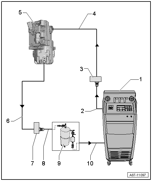
- A/C Service Station
- With electronics and a flushing program, A/C Service Station With Flushing Device. Refer to Parts Information (Tools; Special Tools and Equipment: A/C and Heating).
- If an A/C service station without a flushing program is used, the procedure must be performed manually (evacuate, flush three times with at least 2 kg refrigerant each and extract refrigerant again, evacuate).
- A/C Service Station Refrigerant Hose
- From the high pressure side of the A/C service station (mostly colored red) to the connection for the low pressure side of the A/C compressor on the refrigerant circuit (larger diameter).
- Adapter to the Connection for the Low Pressure Side on the A/C Compressor
- There are different versions depending on the vehicle. Refer to ADAPTER FOR ASSEMBLING FLUSHING CIRCUIT .
- Use the adapter from the Refrigerant Circuits Adapter Set 1 :VAS6338/1 (here the Adapter :VAS6338/41 ).
- Refrigerant Line
- For connecting the A/C compressor to the adapter -item 3-.NOTE:
Only use the refrigerant line when the Adapter :VAS6338/41 is not available.
If the Adapter :VAS6338/41 is not available to remove the flushing circuit, for example remove the refrigerant lines to the condenser, from the vehicle (or use a refrigerant line with the part number 7L6 820 744 AD). Refer to the Parts Information).
- For connecting the A/C compressor to the adapter -item 3-.
- Electrically-Driven A/C Compressor
- The A/C compressor is flushed in the flow direction (from the low pressure side input to the high pressure side output)
- So that as much refrigerant oil as possible is flushed out from the A/C compressor, the A/C compressor must be positioned so that the high pressure side output is as low as possibleCAUTION:
Risk to A/C service station function depending on the version and the amount of refrigerant oil in the A/C compressor
- Depending on the A/C service station version, the oil amount that is deposited in one step may be limited (100 cm3 , for example). Pay attention to the A/C service station operating instructions and technical product description.
- Depending on the A/C compressor, a larger amount of refrigerant oil (for example, 290 cm3 on an Audi Q7 e-tron) may be filled in a new A/C compressor (refer to REFRIGERANT OIL CAPACITIES and COMPRESSOR, REPLACING WITHOUT THE NEED FOR FLUSHING REFRIGERANT CIRCUIT ).
- On a new A/C compressor that is filled with more than 150 cm3 , pour out as much refrigerant oil as possible (via the high and low pressure connection) into a clean container before flushing. This prevents the A/C service station oil separator from overfilling during the flushing procedure.
- Then flush the rest of the refrigerant oil out of the A/C compressor.
NOTE:If the clean refrigerant oil is poured out of a new A/C compressor into a clean container and the A/C compressor is then sealed air-tight, this refrigerant oil can be reused to adjust the amount of refrigerant oil in the circuit.
- Refrigerant Line
- For connecting the A/C compressor to the adapter -item 7-.NOTE:
Only use the refrigerant line when the Adapter :VAS6338/40 is not available.
If the Adapter :VAS6338/40 is not available to remove the flushing circuit, use for example, a refrigerant line with the part number 7L6 820 721 BF or 4G0 260 701 AB. Refer to Parts Information.
- For connecting the A/C compressor to the adapter -item 7-.
- Adapter to the High Pressure Side Connection on the Refrigerant Circuit
- There are different versions depending on the vehicle. Refer to ADAPTER FOR ASSEMBLING FLUSHING CIRCUIT .
- Use the adapter from the Refrigerant Circuits Adapter Set 1 :VAS6338/1 (here the Adapter :VAS6338/40 ).
- Charging Hose for Refrigerant Circuit Flushing Device
- From the connection to the high pressure side of the A/C compressor on the refrigerant circuit (smaller diameter) to the input of the refrigerant circuit flushing device.
- Refrigerant Circuit Flushing Device
- There are different versions of the Refrigerant Circuit Flushing Device. Refer to the Parts Information (Tools; Special Tools and Equipment: A/C and Heating).
- With filter, viewing glass, safety valve, heater, refrigerant reservoir, etc. (depending on version).
- Depending on the construction of the A/C service station and of refrigerant circuit flushing device, a check-valve may be installed at output of refrigerant circuit flushing device (to guarantee correct direction of refrigerant flow during flushing).
- Depending on the design of the refrigerant circuit flushing device, a connection for a refrigerant circuit service coupling may be located at the outlet (and possibly also at the inlet) of the flushing device (instead of a 5/8-18 UNF external thread). If a service connection with a valve is installed on the outlet of the flushing device, this valve must be all the way open when the service coupling is attached (a partially opened valve creates a constriction). If there is a connection for a service coupling on the inlet of the flushing device, the inlet must be modified so that the refrigerant hose coming from the vehicle can be directly connected (a service coupling and a valve in the flushing device inlet create a constriction that impedes the flow of refrigerant from the vehicle to the flushing device and thus the flushing procedure).CAUTION:
Risk of icing over the output of the flushing device via the installed valve which is not correctly opened.
- A partially opened valve installed in this connection creates a constriction that impairs the flow of refrigerant in the flushing device and can ice over due to severe cooling.
- If there is a service connection with a valve on the outlet of the flushing device, this valve must be all the way open during the flushing procedure.
- If there is too strong of cooling (icing over) at the outlet of the flushing device during the flushing procedure, stop the flushing procedure and evacuate the refrigerant from the flushing device and the vehicle via the high and low pressure side. Check the valve in the outlet of the flushing device and service it if necessary.
Risk of icing on the input of the flushing device due to a constriction which is created via a service coupling and in a service connection installed valve.
- Remove the service connection installed on this connection, and connect the service hose that comes from the vehicle directly (without constriction) to the flushing device, possibly using a necessary adapter (depending on the inlet thread of the flushing device).
- A/C Service Station Refrigerant Hose
- From the A/C service station low pressure side (mostly blue) to the outlet of the refrigerant circuit flushing device.