Electrically Driven A/C Compressor, Cleaning
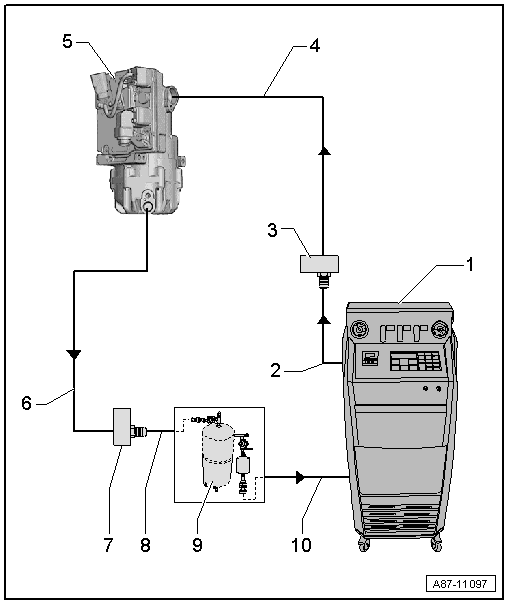
Vehicles with a High-Voltage System
Observe all of the additional warnings for all work performed on vehicles with the high-voltage system. Refer to the appropriate service information .
If it is necessary to perform work in the vicinity of high-voltage system components, "visually inspect" the high-voltage components and cables for damage and follow the "general warnings when working on the high-voltage system". Refer to the appropriate service information .
If it is necessary to perform work on the high-voltage system components, de-energize the high-voltage system and observe the "High-Voltage System General Warnings". Refer to the appropriate service information).
Rinse the A/C Compressor
The refrigerant oil cannot be poured out for electrically driven A/C compressors (there is no oil drain plug) nor can it be poured out during the removal of the compressor.
The refrigerant oil is removed by flushing in the flow direction for electrically driven A/C compressors (because of the installed valve it is not possible to flush against the flow direction).
To flush, arrange the A/C compressor so that the connection for the refrigerant line on the high pressure side is as low as possible.
On a new A/C compressor that is filled with more than 100 cm3 , pour out as much refrigerant oil as possible before flushing -item 5-.
- A/C Service Station
- Use electronics and a program to flush the A/C service station with flushing device. Refer to the Parts Information.
- If an A/C service station without a flushing program is used, the procedure must be performed manually (evacuate, flush four times with at least 2 kg refrigerant for each and extract the refrigerant again, evacuate).
- Refrigerant Hose for A/C Service Station
- From the high pressure side of the A/C service station (mostly red colored) to the low pressure side connection of the A/C compressor on refrigerant circuit (larger diameter).
- Adapter to the Connection for the Low Pressure Side on the A/C Compressor
- There are different versions depending on vehicle. Refer to ADAPTER FOR ASSEMBLING FLUSHING CIRCUIT .
- Use the Refrigerant Circuits Adapter Set - Adapter 48 :VAS6338/48 between the refrigerant hose -2- and the adapter -3-.
- From the VW/Audi - passenger vehicle adapter set (for example the Adapter :VAS6338/41 )
- Refrigerant Line
- To the A/C compressor connection on the adapter -item 3-
- Electrically-Driven A/C Compressor
- The A/C compressor is flushed in the flow direction (from the low pressure side input to the high pressure side output)
- So that as much refrigerant oil as possible is flushed out from the A/C compressor, the A/C compressor must be positioned so that the high pressure side output is as low as possibleNOTE:
Depending on the A/C compressor a larger refrigerant oil quantity can be filled in a new A/C compressor. Refer to REFRIGERANT OIL CAPACITY and the manufacturer on the A/C compressor.
On a new A/C compressor that is filled with more than 100 cm3 , pour out as much refrigerant oil as possible before flushing.
Reason: depending on the A/C service station version, the oil amount that is deposited/separated in one step may be limited.
NOTE:If clean refrigerant oil is emptied from a new A/C compressor in a clean container and this is closed air tight, this can be reused to adjust the refrigerant oil quantity in the circuit.
- Refrigerant Line
- To the A/C compressor connection on the adapter -item 7-
- To remove the flushing circuit use for example a refrigerant line with the part number 7L6 820 721 BF. Refer to the Parts Information.
- Adapter to the Connection for the High Pressure Side on the Refrigerant Circuit
- There are different versions depending on vehicle. Refer to ADAPTER FOR ASSEMBLING FLUSHING CIRCUIT .
- From the VW/Audi - passenger vehicle adapter set (for example the Adapter :VAS6338/40 )
- Filler Hose for Refrigerant Circuit Flushing Device
- From the connection to the high pressure side of the A/C compressor on the refrigerant circuit (smaller diameter) to the input of the refrigerant circuit flushing device.
- Refrigerant Circuit Flushing Device
- There are different versions of the refrigerant circuit flushing device. Refer to the Parts Information (Tools; Special Tools and Equipment: A/C and Heating).
- With filter, viewing glass, safety valve, heater, refrigerant reservoir, etc. (depending on version).
- Depending on the design of the A/C service station and the flushing device for the refrigerant circuits, a connection for a service coupling for the refrigerant circuits can be installed on the output and may also be installed on the input of the flushing device. If on the output of the flushing device a service connection with valve is installed this valve must be completely opened when the service coupling is connected. A valve that is not completely opened creates a constriction.
- If on the input of the flushing device a connection for a service coupling is present, modify the input so that the refrigerant hose which comes from the vehicle can be directly connected.NOTE:
A service coupling and a valve in the flushing device input makes a constriction which impairs the refrigerant flow from the vehicle in the flushing device.
- Refrigerant Hose for A/C Service Station
- From the low pressure side of the A/C service station (mostly blue colored) to the output of the refrigerant circuit flushing device.