Pressures and Temperatures in the Refrigerant Circuit with Expansion Valve
In the following Log (p), h diagram (logarithmic pressure, energy diagram) the procedure is shown, how it flows in the refrigerant circuit for a specific operating condition. Depending on the ambient conditions (engine speed, ambient temperature, specified cooling output etc.) these values change.
The Log (p), h diagram shows the pressure (0 to 60 in bar (0 to 870 psi) absolute pressure) and the energy content (100 to 420 specific enthalpy in kilojoule per kg of the refrigerant R1234yf) in the refrigerant circuit cycle.
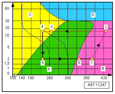
The arrows show the refrigerant flow direction in the refrigerant circuit.
A - Area with Vaporous Refrigerant
B - Area with Gas Refrigerant
C - Area with Liquid Refrigerant
D - Super critical pressure and temperature area, the aggregate state of refrigerant is unspecified (there is no more separation between the fluid and gas refrigerant)
- Low pressure side: output inner heat exchanger, A/C compressor input, the refrigerant is completely evaporated and gas the temperature of the refrigerant is at approximately -4 °C (24.8 °F)
- High pressure side: A/C compressor output, A/C compressor input, the refrigerant was sealed and gas, the temperature of the refrigerant is at approximately 80 °C (176 °F)
- High pressure side: condenser output (receiver/dryer), inner heat exchanger input, the refrigerant is cooled and fluid the temperature of the refrigerant is at approximately 55 °C (131 °F)
- High pressure side: inner heat exchanger output, expansion valve input, the liquid refrigerant was cooled and the refrigerant temperature is at approximately 50 °C (122 °F)
- Low pressure side: evaporator expansion valve, evaporator input, the liquid refrigerant has released the tension and begins to evaporate, the temperature of the refrigerant is at approximately -7 °C (19.4 °F)
- Low pressure side: evaporator output, expansion valve, inner heat exchanger input, the refrigerant is essentially evaporated, a small part is still vapor, the temperature of the refrigerant is at approximately -6 °C (21.2 °F)
The specified temperature correspond to the refrigerant in the refrigerant circuit. Through heat absorption and the heat emission and changes the temperature on the surface of the refrigerant from the components.
The pressure (and the temperature) in refrigerant circuits is maintained at approximately 3 bar (43.5 psi) absolute pressure (corresponds to approximately 2 bar (29 psi) positive pressure), regulated by A/C compressor, even though heat transfer changes and engine speeds vary. However, this applies only within the performance range of the A/C compressor; if the performance limits of the A/C compressor are exceeded, the pressure (and the temperature) increases. Refer to PRESSURES, CHECKING .
On A/C compressors which do not regulate their output themselves, the pressure on the low pressure side and with this the evaporator temperature are regulated by the corresponding control module via the A/C Compressor Regulator Valve -N280-. If depending on the version and the adjustment a temperature in the air downstream from evaporator is smaller than 2 °C (35.6 °F) is measured, the output of the A/C compressor is reduced, under 0 °C (32 °F) the activation of the A/C Compressor Regulator Valve -N280- is switched off. This prevents the evaporator from cooling to sharply or icing.
Temperature and pressure in the refrigerant circuit also on the second evaporator, in vehicles with two evaporators and two expansion valves correspond to those in vehicles with only one evaporator and one expansion valve (parallel switching).
Depending on the version of the refrigerant circuit a component with the inner heater core is installed. Inside the inner heat exchanger, the flowing fluid warm refrigerant on the high pressure side is delivered into the low pressure side as flowing, vapor, cold refrigerant to increase the efficiency of the A/C system. Refer to REFRIGERANT LINE WITH INNER HEAT EXCHANGER .
Depending on the version of the control module (for example the Front A/C Display Control Head -E87- or the Climatronic Control Module -J255-), the measured ambient conditions (exterior temperature, moisture in the vehicle interior etc.) and from the adjustment on the control module (vehicle interior temperature, mode etc.) the pressure and with this the temperature on the evaporator output are regulated to a higher value. Use the Vehicle Diagnostic Tester in the"Guided Fault Finding" function of the A/C system.