Refrigerant Circuit, Evacuating With A/C Service Station
- The work procedure is always to be performed as described in the operating instructions for the A/C service station.
- The quantity of refrigerant oil in the refrigerant circuit is checked and if necessary corrected. Refer to REFRIGERANT R134A CAPACITIES, REFRIGERANT OIL AND APPROVED REFRIGERANT OILS .
- The quantity of refrigerant in the A/C service station is checked.
The refrigerant circuit must be evacuated before it is filled with refrigerant (vacuum). Moisture is also extracted from the circuit.
Leaks may be found when evacuating the refrigerant circuit.
Evacuating:
- Do not start the engine during the evacuation process or when there is a vacuum in the refrigerant circuit.
- The A/C compressor could be damaged if the engine is started when there is a vacuum in the refrigerant circuit.
- Only start the engine when the refrigerant circuit is charged.
-- On vehicles with a high-voltage system, switch off (deactivate) the "auxiliary climate control" function. Refer to the Owner's Manual and Infotainment/MMI Operating Manual.
-- Switch off the ignition.
-- Connect the A/C service station to the power supply.
-- Connect the A/C service station charging hoses to the vehicle refrigerant circuit with the quick-release coupling adapter. Refer to Refrigerant Circuit .
-- Install the hand wheel on the quick-release coupling adapter far enough so that the valves in the service connections are securely open. Do not put too much pressure on the valve.
If pressure is to be measured after charging the system on vehicles that only have a service connection on one side of the refrigerant circuit, use the valve adapter and charging hose with valve opener. Refer to A/C SERVICE STATION, CONNECTING .
Also for vehicles with electrically operated valves in the refrigerant circuit that cannot be opened without current (for example the Audi Q7 e-tron):
For vehicles with a high-voltage system and additional A/C system functions ("heat pump operation" or "cooling the high-voltage battery"), valves may be installed in the refrigerant circuit that cannot be opened without current. These valves are opened and closed via stepper motors, for example, and are no longer activated after switching off the ignition. To completely discharge, correctly evacuate and charge the refrigerant circuit, no sections may be closed. Therefore these valves must be opened before performing this work. Refer to Refrigerant Circuit and use the Vehicle Diagnostic Tester in the"Guided Fault Finding" function.
The check valves in the refrigerant circuit have a specified residual pressure (approximately 0.1 bar or 100 mbar) in the flow direction. So that the refrigerant circuit can be completely evacuated (residual pressure less than 5 mbar), all electrically activated valves must be opened.
-- Open the electrically activated valves (not open without current) using the Vehicle Diagnostic Tester in the"Guided Fault Finding" function.
All
-- Turn on the A/C service station and evacuate the refrigerant circuit for at least 30 minutes. The pressure indicator must indicate an absolute pressure of less than 10 mbar (corresponding to 990 mbar vacuum).
At this pressure, both green LEDs light up, for example, on the :VAG1885 . For currently available A/C service stations. Refer to the Parts Information (Tools; Special Tools and Equipment: A/C and Heating).
-- Turn off the A/C service station and allow it to stand for at least one hour.
- If the vacuum indicator (LED chain) does not change, the system is free of leaks and can be charged.
A current vacuum reading (LED) is only obtained using the :VAG1885 , for example, after pressing the Evacuate button again. For currently available service stations. Refer to the Parts Information (Tools; Special Tools and Equipment: A/C and Heating).
On this A/C service station, if the upper (green) LEDs do not illuminate immediately after turning on, either the refrigerant circuit is leaking or there is still residual moisture/refrigerant in the refrigerant circuit.
If the vacuum is not maintained or if a sufficient vacuum cannot be generated, perform the following:
- If the pressure in refrigerant circuit only increases slowly after evacuating, for example, due to evaporating refrigerant from the refrigerant oil:
-- If there is any doubt as to whether or not the refrigerant circuit has leaks, evacuate again and monitor the vacuum indicator for a longer period of time. Only when the vacuum is maintained can the refrigerant circuit be charged.
-- If it is certain that the refrigerant circuit does not have any leaks, it can be charged.
- If there is a large enough leak that allowed enough air to enter during evacuation that the A/C service station cannot generate a sufficient vacuum or that the vacuum is lost immediately after switching the A/C service station off:
-- Determine the location of the leak in the refrigerant circuit as follows:
A large leak can be identified, for example, if a pressure of maximum 15 bar can be generated in the refrigerant circuit using clean, dry compressed air or nitrogen. Refer to REFRIGERANT CIRCUIT, FLUSHING WITH COMPRESSED AIR AND NITROGEN . If the leak is large enough, the sound of escaping air or gas can be heard at the location of the leak.
Add the compressed air or nitrogen to the closed refrigerant circuit through the service connection after fitting it with a quick-release connector adapter.
 Courtesy of AUDI OF AMERICA, LLC
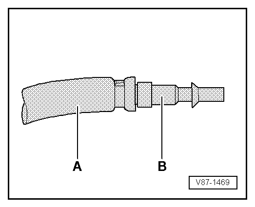
The quick-release coupling adapter for service connections can be connected to the workshop compressor unit, for example, using a modified charging hose -A- (for example, with 5/8" 18 UNF threads, depending on the threads on the quick-release coupling adapter) and a suitable adapter -B-. Refer to IMPROVISED TOOLS . This keeps the moisture, oil and dirt from the workshop compressor unit from getting into the A/C system refrigerant circuit. Also use a combination fine-mesh filter for compressor units that separates out oil, dirt and water, such as those that are standard in paint shops. Install it between the compressor unit and the charging hose -A-. Refer to the Parts Information (Tools; Special Tools and Equipment: A/C and Heating)
 Courtesy of AUDI OF AMERICA, LLC
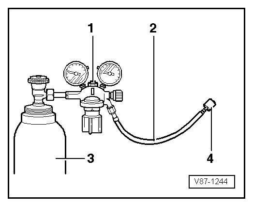
A compressed gas cylinder filled with nitrogen -3- can be connected to the closed refrigerant circuit using a pressure gauge battery with a pressure reducer for nitrogen (maximum reduction pressure: 15 bar (217.5 psi) -1- and with a charging hose -2- (for example, with 5/8" 18 UNF threads) connected to the service connection (to which a quick-release coupling adapter for service connections is connected. Refer to COMMERCIALLY AVAILABLE TOOLS AND MATERIALS .
-- Slowly increase the pressure in the refrigerant circuit to a maximum of 15 bar (217.5 psi).
- Nitrogen can leak uncontrolled from the cylinder.
- Only use pressure reducers for nitrogen cylinders (maximum work pressure 15 bar (217.5 psi)).
- When testing for leaks with nitrogen (maximum permissible pressure 15 bar (217.5 psi)), only work with a pressure reducer for nitrogen cylinders.
- Use appropriate extraction units to draw off the gas mixture escaping from the components.
-- Find the location of the leak by listening for the sound of venting gas.
-- Repair the leak.
-- Evacuate and again monitor the vacuum indicator over a period of hours. Only when the vacuum is maintained can the refrigerant circuit be charged.
- If there is a leak that is small enough that little or no air vents through it and the A/C service station can generate a sufficient vacuum: The vacuum indicator does not increase after switching the A/C system service station or only increases very slowly, indicating that air is only entering through a small leak.
-- Add 100 grams of refrigerant to the circuit, find the location of the leak using an electronic leak detector and repair it or add UV contrast dye to the refrigerant and find the location of the leak using the :VAS6201 and repair it. Refer to REFRIGERANT CIRCUIT, TRACING LEAKS USING ELECTRONIC LEAK DETECTOR (FOR EXAMPLE, and LEAK DETECTION ON REFRIGERANT CIRCUIT USING Leak Detection Kit .
-- Discharge the refrigerant circuit, if necessary. Refer to REFRIGERANT CIRCUIT, DISCHARGING WITH A/C SERVICE STATION .
-- Evacuate the refrigerant circuit and monitor the vacuum indicator again over several hours. Only when the vacuum is maintained can the refrigerant circuit be charged.