System Overview - Refrigerant Circuit With Electrically-Driven A/C Compressor (With Or Without Battery Cooling Module)
NOTE:
The arrows indicate the refrigerant flow direction.
The following illustration shows a refrigerant circuit with an expansion valve and a second evaporator for cooling the battery and an inner heat exchanger as an example.
The layout of the refrigerant circuit is vehicle-specific. Refer to Refrigerant Circuit .
HD = High Pressure Side
ND = Low Pressure Side
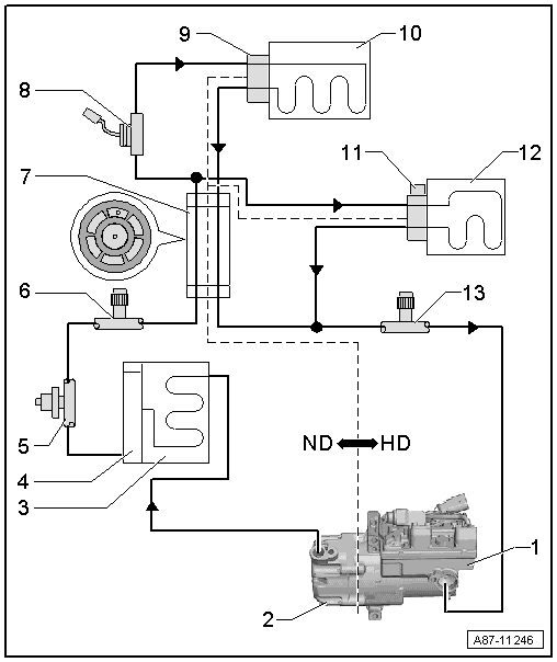
- Electrically-Driven A/C Compressor
- With A/C Compressor Control Module -J842- and Electrical A/C Compressor -V470-. Refer to Refrigerant Circuit .
- Pressure Relief Valve
- Condenser
- With receiver/dryer and dryer cartridge.
- Receiver/Dryer
- Is a component of the condenser
- Refrigerant Pressure Sensor
- Vehicle-specific versions. Refer to Refrigerant Circuit .
- Service Connection - High Pressure Side
- With closure cap.
- Refrigerant Line with Inner Heat Exchanger
- Refrigerant Shut-Off Valve
- Different names. Refer to Refrigerant Circuit .
- Only on vehicles with a battery cooling module for the Hybrid Battery Unit -AX1-.NOTE:
The Refrigerant Shut-Off Valve is for example activated, if the battery needs to be cooled and the vehicle interior is not already being cooled (open without activation).
- Expansion Valve
- On the heater and A/C unit evaporator
- Front Evaporator
- Heater and A/C unit evaporator
- Expansion Valve with Shut-Off Valve
- Different names. Refer to Refrigerant Circuit .
- On the evaporator in the battery cooling module
- Only on vehicles with a battery cooling module for the Hybrid Battery Unit -AX1-.NOTE:
The Expansion Valve with Shut-Off Valve is activated when it is necessary to cool the battery (closed without activation).
- Evaporator
- Evaporator in the battery cooling module
- Only on vehicles with a battery cooling module for the Hybrid Battery Unit -AX1-.
- Service Connection - Low Pressure Side
- With closure cap