Quick-Release Coupling Connections On Refrigerant Circuit: Notes
Service Connections with Schrader Valve (Needle Valve or Push Pin)
 Courtesy of AUDI OF AMERICA, LLC
- Only valves and connections that are resistant to refrigerant R1234yf and refrigerant oil must be installed.
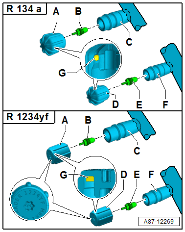
- The service connections -C and F- on a R1234yf refrigerant circuit are designed so that the service connections from a R134a refrigerant circuit designed service couplings cannot be connected.
- Different connections (outer diameter) for high pressure and low pressure side -C and F-.
- Discharge the refrigerant circuit before removing valves or valve inserts -B and E-.
- Always install the closure caps -A and D- with the seal -G-.
Allocation in the vehicle. Refer to Refrigerant Circuit .
-- Extract the refrigerant before removing the valves.
- Low pressure side service connection -F-
- High pressure side service connection -C-
- Valve insert (Designation: Schrader valve or needle valve)
- Closure cap: low pressure side service connection with seal -A-
- Closure cap: high pressure side service connection with seal -D-
After connecting, install the hand wheel for the service coupling just far enough into the quick-release coupling adapter until the valve is securely opened inside the service connection (pay attention to the pressure gauge, do not put too much pressure on the valve).
The service connections on a R1234yf refrigerant circuit are designed so that the service connections from a R134a refrigerant circuit designed service couplings cannot be connected.
The service connections are for example soldered into a refrigerant line and therefore cannot be replaced separately.
To remove and install the valve insert when the refrigerant circuit is discharged, use, for example, an adapter from the Refrigerant Sockets :T10364 .
Tighten the valve insert very carefully because the tightening specification is very small.
There are different versions of these valves and therefore there are different tightening specifications. Valve insert -C- with a VG5 (5.2 x 0.7 mm, tire valve) thread has a tightening specification of 0.4 Nm ± 0.1 Nm; a valve insert with a M6 x 0.75 mm thread has a tightening specification of 0.9 Nm ± 0.1 Nm, and a valve insert with a M8 x 1.0 mm thread has a tightening specification of 2.0 Nm ± 0.2 Nm.
There are different versions of these valve caps, which means there are different tightening specifications. A valve cap with an M8 x 1 mm or M10 x 1 mm thread has a tightening specification of 0.4 Nm ± 0.1 Nm.
There are different versions of these valves, valve inserts and their caps. Make sure the version of the valve inserts and the allocation of the closure caps is correct. Refer to the Parts Information.