Service Connection Measurements
- Valve insert -A- (different versions)
- Service connection -B- (depending on the refrigerant, there are different versions on the high and low pressure side)
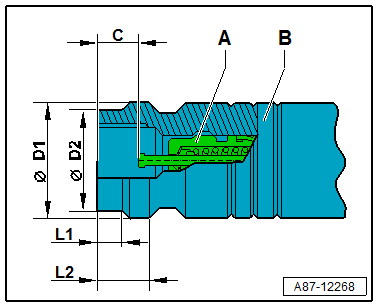
| Service Connection Dimensions -B- | Refrigerant R134a Service Connection | Refrigerant R1234yf Service Connection | ||
|---|---|---|---|---|
| High Pressure Side | Low Pressure Side | High Pressure Side | Low Pressure Side | |
| Outer diameter -D1- | 16.0 mm | 13.0 mm | 17.0 mm | 14.0 mm |
| Outer diameter -D2- | 14.0 mm | 11.0 mm | 13.0 mm | 12.0 mm |
| Section -L1- | 4.6 mm | 6.15 mm | 9.0 mm | 4.75 mm |
| Section -L2- | 8.16 mm | 9.16 mm | 12.5 mm | 7.2 mm |
| Valve installation position (not actuated) -C- | 6.1 to 7.1 mm | 6.1 to 7.1 mm | 8.3 to 9.3 mm | 8.3 to 9.3 mm |
Service Connections with Primary Sealing Valve (Ball Valve)
- This type of service connections is currently not used on VW/Audi refrigerant circuits.
- Only valves and connections that are resistant to refrigerant R1234yf and refrigerant oil must be installed.
- The service connections on a R1234yf refrigerant circuit are designed so that the service connections from a R134a refrigerant circuit designed service couplings cannot be connected.
- Different connections (outer diameter) for high pressure and low pressure side.
- Discharge the refrigerant circuit before removing valves or valve inserts.
- Always install the closure caps with a seal.
Allocation in the vehicle. Refer to Refrigerant Circuit .
Connection with High-Pressure Valve
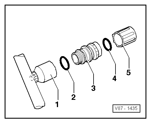
- Socket with internal thread (soldered in)
- Seal (version and identification: black or colored. Refer to the Parts Information)
- Valve with an external thread and groove for the Seal (identification: ball valve)
- Closure Cap Seal
- Closure Cap
After connecting, install the hand wheel for the service coupling just far enough into the quick-release coupling adapter until the valve is securely opened inside the service connection (pay attention to the pressure gauge, do not put too much pressure on the valve).
For removing and installing the valve -3- when the refrigerant circuit is evacuated, for example, use an adapter from the Refrigerant Sockets :T10364 .
There are different versions of these valves (with internal or external threads). Therefore the tightening specifications can also differ. The valves -3- with an M12 x 1.5 mm external thread have a tightening specification of 9 Nm ±1 Nm.
There are different versions of these valves and their caps. Make sure the valve version and the closure cap allocation are correct. Refer to the Parts Information.
Connection with Low-Pressure Valve
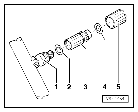
- Socket with an External Thread and Groove for Seal (soldered in)
- Seal (version and identification: black or colored. Refer to the Parts Information)
- Valve with an internal thread
- Closure Cap Seal
- Closure Cap
Install the hand wheel for the service coupling just far enough into the quick-release coupling adapter until the valve is securely opened inside the service connection (pay attention to the pressure gauge, do not put too much pressure on the valve).
For removing and installing the valve -3- when the refrigerant circuit is evacuated, for example, use an adapter from the Refrigerant Sockets :T10364 .
There are different versions of these valves (with internal or external threads). Therefore the tightening specifications can also differ. The currently used valves -3- with an M10 x 1.25 mm internal thread have a tightening specification of 9 Nm ± 1 Nm.
There are different versions of these valves and their caps. Make sure the valve version and the closure cap allocation are correct. Refer to the Parts Information.