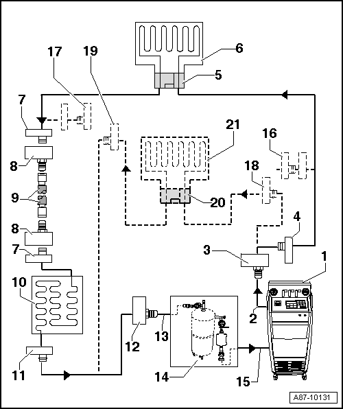
Connection Diagram For Cleaning (Flushing), Refrigerant Circuit With Expansion Valve And Receiver/Dryer
- With 1 or 2 evaporators
- Without or with high-voltage system
The arrows in the following illustrations show the refrigerant flow direction during flushing (refrigerant flows in opposite direction of flow when A/C system is in operation while flushing, therefore the high pressure side of the A/C Service System is connected to the low pressure connection of the refrigerant circuit to the A/C compressor).
This main wiring diagram shows a refrigerant circuit with expansion valve, receiver/dryer and second evaporator (optional equipment on certain vehicles).
On vehicles with an expansion valve and receiver/dryer, the expansion valve is removed and replaced by an adapter. Depending on the vehicle, the receiver/dryer must also be removed and line connections to fluid reservoir be connected to each other by two adapters and a charge hose.
On a vehicle with only one evaporator, components from item "16" are not present or are not needed.
Depending on the construction of the A/C Service Station, check valves may be installed between the refrigerant circuit and the A/C Service Station (to guarantee the correct direction of refrigerant flow during flushing).
The adapter from the VW/Audi - Passenger Vehicle Adapter Set are provided with 5/8" -18 UNF threads use additional adapters from the VW/Audi - Passenger Vehicle Adapter Set so that the R1234yf -A/C Service Station filling hose can be attached. Refer to the Parts Information.
On vehicles with a high-voltage system power-operated valves are installed in the refrigerant circuit, which must be removed to clean (flush) and replaced with hand shut-off valves or adapters. Refer to Refrigerant Circuit .
- A/C Service Station
- With electronics and a flushing program, A/C Service Station with flushing device. Refer to the Parts Information (Tools; Special Tools and Equipment: A/C and Heating).
- If an A/C Service Station without a flushing program is used, the procedure must be performed manually (evacuate, flush four times with at least 3 kg refrigerant for each and extract the refrigerant again, evacuate).
- Refrigerant Hose for A/C Service Station
- From the high pressure side of the A/C Service Station (mostly red colored) to the low pressure side connection of the A/C compressor on refrigerant circuit (larger diameter).
- Adapter to Connection for Low Pressure Side on Refrigerant Circuit
- There are different versions depending on vehicle. Refer to ADAPTER FOR ASSEMBLING FLUSHING CIRCUIT .
- Use the Refrigerant Circuits Adapter Set - Adapter 48 :VAS6338/48 between the refrigerant hose -2- and the adapter -3-.
- From the VW/Audi - Passenger Vehicle Adapter Set.
- Depending on the version of the adapter an additional adapter is necessary to connect the A/C Service Station filling hose.NOTE:
The A/C Service Station filler hose has a M12 x 1.5-6G external thread according to SAE J639 on the adapter to the connection for the low pressure side an 5/8 -18 UNF external thread is available. An additional adapter is necessary so that both components can be connected. Refer to the Parts Information (Tools; Special Tools and Equipment: A/C and Heating).
To reach a maximum possible flow speed, the service coupling is removed from the filler hose to flush (there are constrictions in the service coupling, which significantly reduces the flow speed velocity).
- Low Pressure Side Connection on Refrigerant Circuit
- There are different versions depending on vehicle. Refer to ADAPTER FOR ASSEMBLING FLUSHING CIRCUIT .
- Adapter for Removed Expansion Valve
- There are different versions depending on vehicle. Refer to ADAPTER FOR ASSEMBLING FLUSHING CIRCUIT .
- From the VW/Audi - Passenger Vehicle Adapter Set. Refer to the Parts Information (Tools; Special Tools and Equipment: A/C and Heating).
- Evaporator
- Connection to Receiver/Dryer
- There are different versions depending on vehicle. Refer to ADAPTER FOR ASSEMBLING FLUSHING CIRCUIT .
- Not present on vehicles with a dryer cartridge in the receiver/dryer on the condenser or with a receiver/dryer installed in the condenser. Refer to Refrigerant Circuit .
- Adapter for Bridging Removed Receiver/Dryer
- Not required for all vehicles.
- There are different versions depending on vehicle. Refer to ADAPTER FOR ASSEMBLING FLUSHING CIRCUIT .
- From the VW/Audi - Passenger Vehicle Adapter Set.
- Refrigerant Filler Hose
- Filler Hose (from the VW/Audi - Passenger Vehicle Adapter Set), for example. Refer to ADAPTER FOR ASSEMBLING FLUSHING CIRCUIT .
- Condenser
- If the receiver/dryer is attached directly to the condenser, the receiver/dryer must be removed and replaced only after flushing. Refer to Refrigerant Circuit .
- If a receiver/dryer with dryer cartridge is installed on the condenser, the dryer cartridge must be removed (reseal the receiver/dryer at or in the condenser after removing). Refer to Refrigerant Circuit
.NOTE:
On certain vehicles the receiver/dryer is integrated inside the condenser and the dryer cartridge cannot be replaced separately and is not available as a single part. In this case, replace the condenser with the receiver/dryer / dryer cartridge after flushing on these vehicles. Refer to Refrigerant Circuit and the Parts Information.
- High Pressure Side Connection on Refrigerant Circuit
- There are different versions depending on vehicle. Refer to ADAPTER FOR ASSEMBLING FLUSHING CIRCUIT .
- Adapter to Connection for High Pressure Side on Refrigerant Circuit
- There are different versions depending on vehicle. Refer to ADAPTER FOR ASSEMBLING FLUSHING CIRCUIT .
- From the VW/Audi - Passenger Vehicle Adapter Set.
- Charging Hose for Refrigerant Circuit Flushing Device
- From the connection to the high pressure side of the A/C compressor on the refrigerant circuit (smaller diameter) to the input of the refrigerant circuit flushing device.
- Refrigerant Circuit Flushing Device
- There are different versions of the Refrigerant Circuit Flushing Device. Refer to the Parts Information (Tools; Special Tools and Equipment: A/C and Heating).
- With filter, viewing glass, safety valve, heater, refrigerant reservoir, etc. (depending on version).
- Depending on the construction of the A/C Service Station and of refrigerant circuit flushing device, a check valve may be installed at the output of the refrigerant circuit flushing device (to guarantee correct direction of refrigerant flow during flushing).
- Depending on the flushing device a 5/8 -18 UNF external thread a connection for a R134a or a R1234yf high pressure service coupling can be present on the output for the A/C Service Station.NOTE:
So that the flushing device can be connected on the A/C Service Station on flushing devices with a 5/8 -18 UNF external thread or a connection for a R134a low pressure side service connection an additional adapter is necessary to connect the R1234yf low pressure side service connection or a filler hose to the A/C Service Station (with a M12 x 1.5-6G external thread according to SAE J639) to the output of the flushing device.
The filler hose from the A/C Service Station has a M12 x 1.5-6G external thread according to SAE J639. On the flushing device for the refrigerant circuit there can be a service connection for a low pressure side service connection according to SAE J639 for the refrigerant R1234yf, a M12 x 1.5-6G inner thread according to SAE J639, a service connection for a R134a low pressure side service connection or a 5/8 -18 UNF external thread depending on the version. So that both components can be connected an additional adapter may be necessary. Refer to the Parts Information.
So that the refrigerant with a lower flow speed can be extracted by the A/C Service Station the low pressure side service connection can be used here.
- Refrigerant Hose for A/C Service Station
- From the low pressure side of the A/C Service Station (mostly blue colored) to the output of the refrigerant circuit flushing device.
- Adapter for Sealing Outlet to Second Evaporator
- Only necessary on certain vehicles with optional equipment "second evaporator"
- From the VW/Audi - Passenger Vehicle Adapter Set.
- Adapter for Sealing Outlet to Second Evaporator
- Only necessary on certain vehicles with optional equipment "second evaporator"
- From the VW/Audi - Passenger Vehicle Adapter Set.
- Low Pressure Side Connection on Refrigerant Circuit to Second Evaporator
- There are different versions depending on vehicle. Refer to ADAPTER FOR ASSEMBLING FLUSHING CIRCUIT .
- Only present on certain vehicles with optional equipment "second evaporator"
- High Pressure Side Connection on Refrigerant Circuit to Second Evaporator
- There are different versions depending on the vehicle. Refer to ADAPTER FOR ASSEMBLING FLUSHING CIRCUIT .
- Only present on certain vehicles with optional equipment "second evaporator"
- Adapter for Removed Expansion Valve on Second Evaporator
- There are different versions depending on the vehicle. Refer to ADAPTER FOR ASSEMBLING FLUSHING CIRCUIT .
- Only necessary on certain vehicles with optional equipment "second evaporator"
- From the VW/Audi - Passenger Vehicle Adapter Set.
- Second Evaporator
- Only present on certain vehicles with optional equipment "second evaporator"