Pinion, Adjusting: Notes
Special tools and workshop equipment required
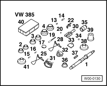
- Measuring Set: VW 385
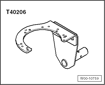
- Gearbox Support: T40206
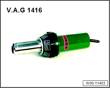
- Hot Air Blower: V.A.G 1416 or Wiring Harness Repair Set - Hot Air Blower: VAS1978/14A
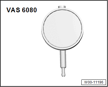
- Dial Gauge for example Dial Gauge - 0-3mm : VAS 6080
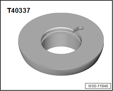
- Centering Plate: T40337
Determining thickness of previous shims "S3 " and "S4 "
-- Secure transmission housing to the Gearbox Support: T40206 . The transmission housing be vertical to do so.
- The differential is removed.
- The double angular contact ball bearing is pressed on the pinion and the preload sleeve with circlip is installed. Refer to DRIVE PINION, DISASSEMBLING AND ASSEMBLING .
- Warm the transmission housing, for example with the Hot Air Blower in the area of the bearing seat -arrow- to approximately 100 °C (212 °F).
- A old (removed) adjusting shim -1- "S 3 " for example 1.05 mm is used temporarily for the initial measurement. It is designated as "S 3 *" in the following. After adjusting the dimensions "R", "S 3 *" is replaced with the final shim "S3 ".
-- Insert the old shim "S 3 *" -1- for example 1.05 mm in the transmission housing.
-- Then insert the pinion -3- quickly by hand without tilting all the way in the transmission housing.
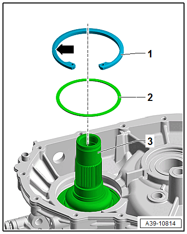
Determine the temporary shim "S 4 " -2- as follows:
Formula: "S 4 " = 2.54 mm - "S 3 "
| Example: | ||
|---|---|---|
| Constant value | 2.54 mm | |
| - | Thickness of old shim "S 3 *" | 1.05 mm |
| = | Thickness of temporary shim "S 4 " | 1.49 mm |
- Insert a 1.49 mm shim "S4 " temporarily for the initial measurement. It is designated as "S 4 *" in the following. After adjusting the dimensions "R", "S 4 *" is replaced with the final shim "S4 ".
-- Place the temporary shim "S 4 *" -2- on the double angular contact ball bearing.
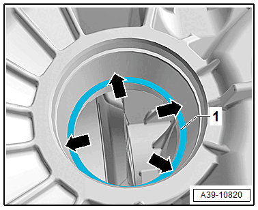
- Installation position of the circlip -1- : the bevel -arrow- points upward and the flat side points to the double angular contact ball bearing.
-- Install the circlip -1- in the transmission housing groove all around.
Adjust the dimension "R"
- The dimension "R" is adjusted to determine the final shim thickness of the "S 3 " and "S 4 " for this drivetrain on the Measuring Set - Adjustable Master Gauge: VW 385/30 .
-- Adjust the setting rings of the Measuring Set - Measuring Bar: VW 385/1 -1- to the following value:
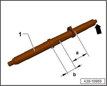
- Dimension -a- = 61 mm (2.40 in.)
- Dimension -b- = 35 mm (1.38 in.)
The dimension -a- is located on the side of the location -arrow- of the Dial Indicator: VAS 6080A .
-- Assemble the Measuring Set - Measuring Bar: VW 385/1 , as shown:
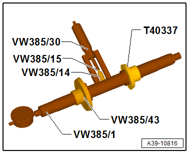
- Measuring Set - Extension Pin - 9.3mm: VW385/15 .
-- Adjust the Measuring Set - Adjustable Master Gauge: VW 385/30 to the dimension "R" = 60.00 mm (2.36 in.) and place on the Measuring Set - Measuring Bar: VW 385/1 .
Tip:
- The dimension "R" generally is for all dimensions 60.00 mm (2.36 in.). There is no individual dimension.
-- Set the dial gauge (3 mm measuring range) to "0" with 2 mm pre-tension.
-- Place the Measuring Set - End Gauge: VW 385/33 -2- on the pinion head -1-.
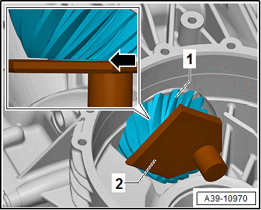
- Pay attention that the Measuring Set - End Gauge: VW 385/33 is precisely installed and free of oil.
- The Measuring Set - End Gauge : VW 385/33 must be flush on the pinion head -arrow- and may not be tilted in the clutch housing.
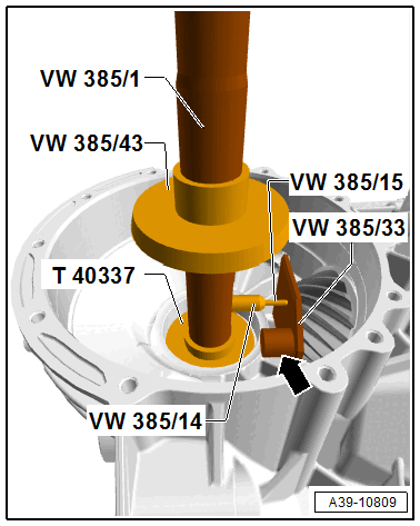
-- Remove the Measuring Set - Adjustable Master Gauge: VW 385/30 and insert the Measuring Set - Measuring Bar: VW 385/1 in the transmission housing.
The Measuring Set - Extension Pin - 9.3mm: VW385/15 must not touch the magnet -arrow- of the Magnetic Plate when turning the Universal Mandrel.
- Dial gauge faces final drive cover.
- The right flange shaft seal is not removed from the final drive cover.
- O-ring is inserted in final drive cover.
-- Position the final drive cover -1- and tighten the four bolts -2- to the tightening specification.
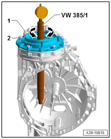
-- Using an adjustable ring, pull the Measuring Set - Centering Plate: T40337 out far enough so that the Universal Mandrel can only just be turned by hand.
-- Turn the Universal Mandrel until the dial gauge tip touches the Magnetic Plate on the head of the pinion and indicates the maximum runout (return point).
- Measured value in the following example: = 0.08 mm (red range)
- Check one more time after removing the Universal Mandrel if the dial gauge, with the 2 mm pre-tension, is at "0" with the Measuring Set - Adjustable Master Gauge: VW 385/30 installed.
Determining thickness of the shim "S 3 "
- If measured in red numbered area, measured value must be subtracted.
- If measured in black numbered area, measured value must be added to it.
Formula:
"S 3 " = "S 3 *" + "measured value" ("measured value" in black numbered area)
"S 3 " = "S 3 *" + "measured value" ("measured value" in red numbered area)
| Example: | ||
|---|---|---|
| Installed shim "S3 *" | 1.05 mm | |
| - | Determined value (red numbered area) | 0.08 mm |
| = | Shim thickness "S 3 " | 0.97 mm |
-- Determine the shim according to the table. Refer to the Parts Information for the part number.