Overview - Hydraulic Control Unit 0D3 And 0BX
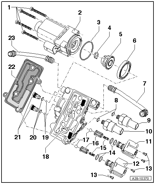
- Bolt
- 5 Nm
- All-Wheel Drive Pump -V415-
- Removing and Installing. Refer to All-Wheel Drive Pump -V415-, REMOVING AND INSTALLING, 0D3 AND 0BX .
- O-Ring
- Always replace.
- Adapter
Tip:
- The adapter could fall out when removing the All-Wheel Drive Pump -V415-.
- Insert the adapter into the recesses in the hydraulic pump before installing the All-Wheel Drive Pump -V415-.
- Hydraulic Pump
- Consists of a guide ring, the housing and six pistons
- Assembling. Refer to Fig 2.
- Ball Bearing
- Can be installed and removed by hand
- Left Line
- Tighten the nuts to 30 Nm.
- Is installed between the hydraulic control unit and the left chamber
- Tighten both nuts hand-tight when installing
- O-Ring
- Always replace.
- Oil Pressure/Temperature Sensor -G437-
- 10 Nm
- Brown connector
- Removing and installing. Refer to Oil Pressure/Temperature Sensor -G437- OR Oil Pressure/Temperature Sensor 2 -G640-, REMOVING AND INSTALLING, 0D3 AND 0BX .
- Oil Pressure/Temperature Sensor 2 -G640-
- 10 Nm
- Black connector
- Removing and installing. Refer to Oil Pressure/Temperature Sensor -G437- OR Oil Pressure/Temperature Sensor 2 -G640-, REMOVING AND INSTALLING, 0D3 AND 0BX .
- All-Wheel Drive Clutch Valve 2 -N446-
- Color: brown
- Removing and installing. Refer to All-Wheel Drive Clutch Valve -N445- OR All-Wheel Drive Clutch Valve 2 -N446-, REMOVING AND INSTALLING, 0BE AND 0BX .
- Installed position, the connector faces upward toward the Oil Pressure/Temperature Sensor --
- All-Wheel Drive Clutch Valve -N445-
- Color: black
- Removing and installing. Refer to All-Wheel Drive Clutch Valve -N445- OR All-Wheel Drive Clutch Valve 2 -N446-, REMOVING AND INSTALLING, 0BE AND 0BX .
- Installed position, the connector faces upward toward the Oil Pressure/Temperature Sensor --
- Bolt
- 2.5 Nm
- O-Ring
- Always replace.
- Mount onto the Clutch Valve --
- Pressure Spring
- Insert into the guide -item : Guide
- Guide
- Installation position, large diameter faced the ball -item : Ball
- Ball
- Insert into the guide before installing -item : Guide
- Hydraulic Control Unit Housing
- With centering pins -arrows-
- The centering pins lock the hydraulic control unit and seal to the final drive housing.
- Ball
- Install in the hole in the shuttle valve before installing -item : Shuttle Valve
- O-Ring
- Always replace.
- Shuttle Valve
- 8 Nm
- Removing and Installing. Refer to Fig 4.
- Seal
- With strainer
- Install on the centering pins in the hydraulic control unit housing
- Right Line
- Tighten the nuts to 30 Nm.
- Is installed between the hydraulic control unit and the right chamber
- Tighten both nuts hand-tight when installing
Assembling the hydraulic pump
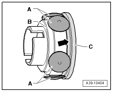
-- Install the six pistons -A- in the housing -B-.
-- Install the guiding ring -C- so that the piston touches the collar -arrow-.
-- Insert the hydraulic pump -1- with the guide ring -2- in the in the hydraulic control unit housing.
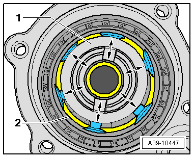
Function test:
-- Turn the hydraulic pump -1- several times. While doing so pay attention to the following:
- When turning the hydraulic pump must not become hooked or tilted.
- All pistons must be removed and pressed in.
Removing and installing the shuttle valves
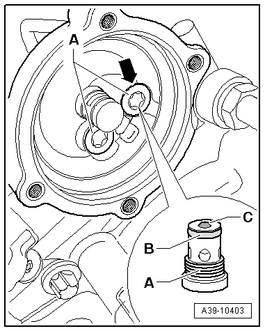
-- Remove the All-Wheel Drive Pump -V415-, hydraulic pump and ball bearing -item : Ball Bearing beforehand.
-- Remove the shuttle valves -A-. Always remove the ball -C- as well.
-- Insert the ball into the hole in the shuttle valve when installing.
-- Install the shuttle valve all the way with a new O-ring -B-.
- The shuttle valve must rest lower than the opposing housing surface -arrow-. If this is not the case, then the remove the valve again and adjust the position of the ball.
-- Tighten the shuttle valve to the tightening specification -item : Shuttle Valve.