Overview - Front Brakes, Steel Brakes 1LC/1LD/1LE/1LF/1LG/1LH
 Courtesy of AUDI OF AMERICA, LLC
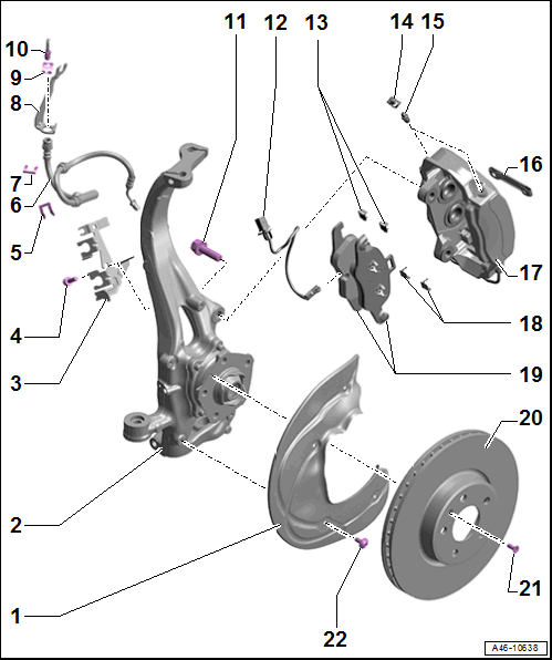
- Brake Shield
- Wheel Bearing Housing
- Bracket
- For brake hose and wire
- Bolt
- 20 Nm
- Replace if damaged
- Replace self-locking bolts and nuts after removing
- Clean before re-using
- Hose Bracket
- For brake hose
- Brake Hose
- Brake hose to brake caliper tightening specification: 14 Nm
- Replace if damaged
- Make sure the brake hose is routed correctly. Make sure the brake hose is not blocked, bent, twisted or rubbing against the vehicle.
- Make sure that tabs are properly seated in the grooves on the bracket.
- Hose Bracket
- Replace if damaged
- Bracket
- For the brake line/hose
- On the body
- Spring
- Replace if damaged
- Brake Line
- Brake line to brake hose tightening specification: 14 Nm
- Replace a damaged or bent brake line
- Do not change the bending shape.
- Bolt
- 200 Nm
- Replace if damaged
- Clean before re-using
- Replace self-locking bolts and nuts after removing
- Brake Pad Wear Indicator Wire
- Replace when replacing the pads
- For the left inner brake pad with the Left Front Brake Pad Wear Sensor -G34-
- Refer to BRAKE PAD WEAR INDICATOR WIRE, REMOVING AND INSTALLING
- Anti-Friction Plate
- Installation position. Refer to Fig 2.
- Protective Cap
- Bleed Screw
- 18 Nm
- Refer to HYDRAULIC SYSTEM, BLEEDING
- Before installing, thinly coat with Assembly Paste :G 052 150 A2 .
- Spring Bracket
- Installing. Refer to Fig 4.
- Brake Caliper
- Allocation. Refer to the Parts Information.
- Refer to BRAKE CALIPER, REMOVING AND INSTALLING, STEEL BRAKES 1LC/1LD/1LE/1LF/1LG/1LH
- Refer to BRAKE CALIPER, REPLACING, STEEL BRAKES 1LC/1LD/1LE/1LF/1LG/1LH
- Servicing. Refer to BRAKE CALIPER PISTON, REMOVING AND INSTALLING, FOUR-PISTON BRAKE .
- Anti-Friction Plate
- Installation position. Refer to Fig 2.
- Brake Pads
- Always replace on both axles.
- Allocation. Refer to the Parts Information.
- Inner brake pads with a mount for the brake pad wear sensor
- Check the pad thickness. For the wear limit. Refer to BRAKE PADS, CHECKING THICKNESS .
- Refer to BRAKE PADS, REMOVING AND INSTALLING, STEEL BRAKES 1LC/1LD/1LE/1LF/1LG/1LH
- Refer to Fig 3
- Brake Rotor
- Allocation. Refer to the Parts Information.
- Wear limit. Refer to TECHNICAL DATA, BRAKES .
- Maximum lateral run-out: 0.06 mm
- If the brake rotor is installed, measure using the Dial Indicator - 0-10mm :VAS6079 and Dial Indicator Bracket :VAS6079/1 .
- Clean away any dirt and rust on the brake rotor, and perform the measurement 10 mm from the outer edge of the brake rotor.
- Do not use excessive force to separate the brake rotor from the wheel hub. Use rust remover, if necessary, otherwise the brake rotor could be damaged.
- Refer to BRAKE ROTOR, REMOVING AND INSTALLING, STEEL BRAKES CAUTION:
Risk of accident due to uneven braking.
- If a brake rotor is damaged or worn, check the other brake rotors for damage and wear.
- Bolt
- 8 Nm
- Replace if damaged
- Replace self-locking bolts and nuts after removing
- Clean before re-using
- Bolt
- 10 Nm
- Replace if damaged
- Replace self-locking bolts and nuts after removing
- Clean before re-using
Anti-Friction Plates Installation Position A
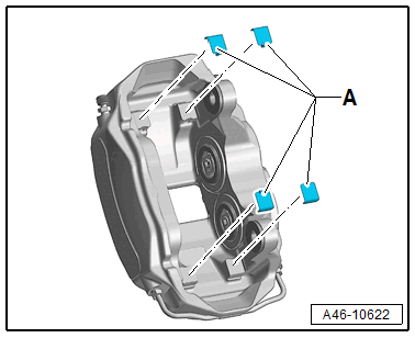
CAUTION:
Risk of malfunction due to missing anti-friction plates.
- Make sure all anti-friction plates are present and in their installation position before inserting the brake pads.
- Insert all four anti-friction plates -A- into the brake pad contact surfaces as shown.
- Anti-friction plate installation position: the small narrow tab faces the brake caliper.
- Make sure the installation position is correct before installing the brake pads.
Brake Pad Installation Position, Steel Brakes 1LC/1LD/1LE/1LF/1LG/1LH
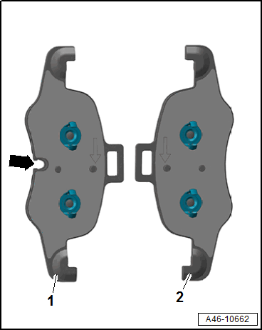 Courtesy of AUDI OF AMERICA, LLC
- Inner brake pad with groove -arrow- for brake pad wear indicator sensor
- Outer Brake Pad
-- Clip the brake pads with the springs into the brake caliper pistons.
Spring Bracket, Installing
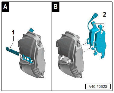
-- After inserting the brake pads -2-, slide the spring bracket -1- onto the brake pads through the eyes and let it engage into the mount.
- The spring bracket must engage audibly and noticeably in the mount in the brake caliper.