Overview - Front Brakes, Ceramic Brakes 1LN/1LU/1LT
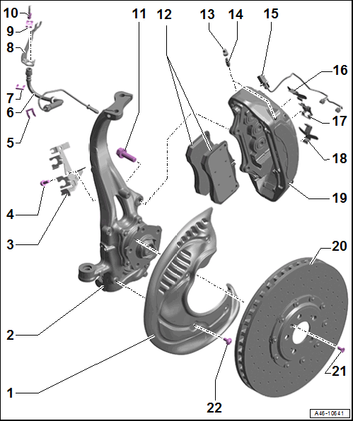
- Brake Shield
- Wheel Bearing Housing
- Bracket
- For brake hose and wire
- Bolt
- 20 Nm
- Hose Bracket
- For brake hose
- Brake Hose
- Brake hose to brake caliper tightening specification: 14 Nm
- Replace if damaged
- Make sure the brake hose is routed correctly. Make sure the brake hose is not blocked, bent, twisted or rubbing against the vehicle.
- Make sure that tabs are properly seated in the grooves on the bracket.
- Hose Bracket
- For brake hose
- Bracket
- For brake hose
- On the body
- Spring
- Replace if damaged
- Brake Line
- Brake line to brake hose tightening specification: 14 Nm
- Bolt
- 200 Nm
- Replace damaged bolts
- Replace the self-locking bolts after removing them
- Clean bolts before reusing
- Brake Pads
- Always replace on both axles.
- Allocation. Refer to the Parts Information.
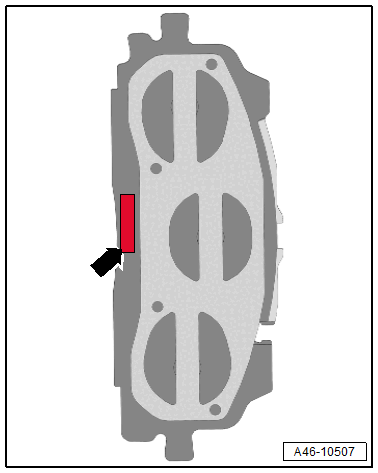
- Inner brake pads with a mount for the brake pad wear sensor
- Check the pad thickness. For the wear limit. Refer to BRAKE PADS, CHECKING THICKNESS .
- Refer to BRAKE PADS, REMOVING AND INSTALLING, CERAMIC BRAKES
- Refer to Figure
- Protective Cap
- Bleed Screw
- 18 Nm
- Refer to HYDRAULIC SYSTEM, BLEEDING
- Before installing, thinly coat with Assembly Paste :G 052 150 A2 .
- Brake Pad Wear Indicator Wire
- For inner and outer brake pads with
- Left Front Brake Pad Wear Sensor -G34-
- Right Front Brake Pad Wear Sensor -G35-
- Replace when replacing the pads
- Refer to BRAKE PAD WEAR INDICATOR WIRE, REMOVING AND INSTALLING
- For inner and outer brake pads with
- Upper Spring
- Replace when replacing the pads
- Note the installation position
- Make sure they are seated correctly in the brake caliper
- Bracket
- For the brake pad wear indicator wire
- Lower Brake Pad Spring
- Replace when replacing the pads
- Note the installation position
- Make sure they are seated correctly in the brake caliper
- Brake Caliper
- Allocation. Refer to the Parts Information.
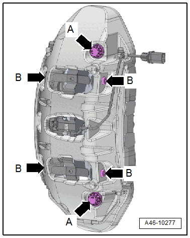
- Do not loosen the threaded connections. Refer to Fig 2.
- Refer to BRAKE CALIPER, REMOVING AND INSTALLING, CERAMIC BRAKES
- Refer to BRAKE CALIPER, REPLACING, CERAMIC BRAKES
- Servicing. Refer to BRAKE CALIPER PISTON, REMOVING AND INSTALLING, SIX-PISTON BRAKE .
- Brake Rotor
- Allocation. Refer to the Parts Information.
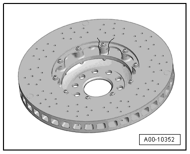
- Do not loosen the threaded connections. Refer to Fig 3.
- To determine the wear. Refer to CERAMIC BRAKE ROTOR, DETERMINING WEAR WITHOUT Carbon-Ceramic Brake Wear Tester or CERAMIC BRAKE ROTOR, DETERMINING WEAR USING Carbon-Ceramic Brake Wear Tester .
- Additionally check for:
- Cracks in connection area. Refer to CRACKS IN CERAMIC BRAKE ROTOR CONNECTION AREA .
- Chamfer. Refer to CHAMFER .
- Nicks. Refer to NICKS ON CERAMIC BRAKE ROTOR .
- Crack in cooling channel. Refer to CRACK IN COOLING CHANNEL .
- Refer to BRAKE ROTOR, REMOVING AND INSTALLING, CERAMIC BRAKES CAUTION:
Risk of accident due to uneven braking.
- If a brake rotor is damaged or worn, check the other brake rotors for damage and wear.
- Make note of the direction of travel
- Bolt
- 8 Nm
- Replace if damaged
- Replace self-locking bolts and nuts after removing
- Clean before re-using
- Bolt
- 10 Nm
- Replace if damaged
- Replace self-locking bolts and nuts after removing
- Clean before re-using
Do Not Loosen the Threaded Connections A and B arrows on the Brake Caliper
 Courtesy of AUDI OF AMERICA, LLC
CAUTION:
Risk of malfunction due to loosened threaded connections.
- Never loosen the bolts and guide pins on the brake caliper.
Do not loosen the threaded connections on the ceramic brake rotor.
CAUTION:
Risk of accident due to loosened ceramic brake rotor threaded connections.
- Never loosen the threaded connections on the ceramic brake rotor.