Rearview Camera -R189-, CALIBRATING
Special tools and workshop equipment required
- Calibration Unit: VAS6350A
- Calibration Tool - Wheel Center Mountings: VAS6350/1
- Calibration Tool - Spacing Laser: VAS6350/2
- Calibration Tool - Linear Laser: VAS6350/3A
- Vehicle Diagnostic Tester
-- Establish the requirements. Refer to Requirements for Calibrating .
-- Connect the Vehicle Diagnostic Tester.
Calibration Tool - Wheel Center Mounting: VAS 6350/1A , Installing
-- Check which hole circle the rims have.
-- Equip the : VAS6350/1 appropriately.
-- To do so, secure the three wheel bolt adapters in the hole for each : VAS6350/1 .
-- Place the paddle on both : VAS6350/1 and secure them using a clamping screw.
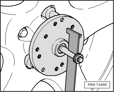
-- Place the : VAS6350/1 onto the wheel bolts on the rear wheels.
The : VAS6350/1 are positioned by the "O-rings" in the adapters and secured.
 Courtesy of AUDI OF AMERICA, LLC
Attach the : VAS6350/1 onto the wheels so that any installed "anti-theft" wheel bolts are not connected to the : VAS6350/1 .
-- Adjust the paddles with the aid of clamping screw so that they move freely just above the floor. Check the paddles for ease of movement.
-- Install and align the : VAS6350A . Refer to Calibration Tool .
Distance Measurement
-- Switch on the : VAS6350/2 .
The following display appears.
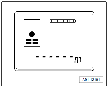
The display shows how to stop the : VAS6350/2 . Press the corresponding button.
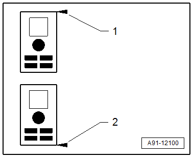
- Attach with Front Edge
- Attach with Rear Edge
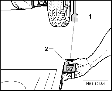
-- Hold the : VAS6350/2 -2- flush in the bracket on one side of the calibration board as shown. The : VAS6350/2 -2- must sit securely on the bracket at the same time.
 Courtesy of AUDI OF AMERICA, LLC
-- Push the measurement button briefly.
The laser switches on.
The laser beam from the : VAS6350/2 -2- must hit the lower, enlarged section of the paddle -1-.
If this is not the case, the paddles must be corrected accordingly via clamping screws on the : VAS6350/1 .
-- Use one hand to secure the : VAS6350/2 in the bracket on the : VAS6350A while the laser beam is visible on the paddle.
-- Then press the measurement button for the distance measurement briefly.
-- Note the read value.
-- Repeat this measurement on the other side of the : VAS6350A in the same way for the rear wheel.
The distance value must be the same on both sides.
If values are not identical:
-- Align the : VAS6350A long enough so that both sides are identical.
-- When adjusting, make sure the : VAS6350/3A strikes the center above the Audi rings and that the level indicator remains centered. Adjust if necessary.
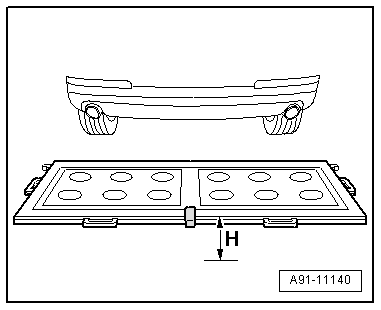
Measurement -Dimension H- :
-- Measure the height of the : VAS6350A , dimension -H- (top edge platform - floor).
Make sure the : VAS6350/2 is adjusted correctly (attach with front edge).
The display shows how to stop the : VAS6350/2 . Press the corresponding button.
- Attach with Front Edge
- Attach with Rear Edge
-- Then with a commercially available folding ruler measure the height of the camera lens center of the rearview camera to the wheel contact surface.
-- Mark the determined height.
The measured distance measurement, the height of the calibration device and the height of the center of the rearview camera lens must be entered in the Vehicle Diagnostic Tester in "mm".
Calibrating Procedure
The Vehicle Diagnostic Tester is connected.
-- Select the Diagnostic mode and start the diagnosis.
-- Select the Test plan tab.
-- Select the Select individual test button and select the following tree structure consecutively:
- Body
- Electrical system
- 01 - OBD-capable systems
- 6C - Rearview camera system control module - J772
- 6C - Rearview camera system control module, functions
- 6C - Calibrating
From here, the Vehicle Diagnostic Tester advances the calibration procedure forward.