Driver Assistance Systems Front Camera, Calibrating
Special tools and workshop equipment required
- Wheel Alignment Computer released by VW/Audi
- Vehicle Diagnostic Tester
- Camera :VAS6331/1
- Setting Device - Basic Set :VAS6430/1A
There are Two Choices for Calibrating:
The "Complete Alignment"
This procedure should be selected for the following activities if a wheel alignment and calibration/adjustment should be performed.
- The rear axle toe was adjusted.
- The vehicle suspension was changed, for example changing from standard to sport suspension.
The "Quick Access"
This procedure should be selected for the following activities if only the calibration/adjustment will be performed.
- The test plan in the Vehicle Diagnostic Tester requires a readjustment.
- The Driver Assistance Systems Front Camera -R242- was removed and installed or replaced.
- The Driver Assistance Systems Front Camera -R242- bracket was removed and installed or replaced.
- The lens was replaced (window heating faulty).
- The inside of the black cut-out was cleaned.
- The wire for the Driver Assistance Systems Front Camera -R242- was replaced.
- The connector for the Driver Assistance Systems Front Camera -R242- was touched.
- The windshield was removed and installed or replaced.
Both procedures are programmed in the wheel alignment computer. The respective procedure is performed automatically. It is only necessary to select the appropriate program for the procedure that will be performed.
If only the front camera should be calibrated/adjusted, then the "quick access" mode must be selected on the wheel alignment computer.
The procedure in the "quick access" mode is described in the following.
Procedure
The procedure is described for a John Bean V3D Aligner :VAS 6331 .
- Observe the test requirements. Refer to AXLE ALIGNMENT TEST REQUIREMENTS .
- Measurement Preparations for Calibrating and Adjusting Driver Assist Systems. Refer to MEASUREMENT PREPARATIONS FOR CALIBRATING/ALIGNING THE DRIVER ASSIST SYSTEMS, QUICK ACCESS MODE .
-- Check if the :VAS6430/1 is in the center position and is locked.
-- Check if the Driver Assistance Systems Front Camera -R242- fits correctly in the bracket and the viewing range for the camera is not blocked.
-- Drive the vehicle "straight" onto the alignment rack. Switch off the ignition when the vehicle has come to a stop.
-- Check the DTC memory for the Driver Assistance Systems Front Camera -R242-. Fix all displayed entries.
-- Position the front wheels so they are straight.
-- Install quick-action clamps on the wheels.
-- Mount the reflectors on the quick-action clamps.
-- Carry out wheel run-out compensation.
-- Select the button for the driver assistance systems front camera calibration procedure in the wheel alignment computer.
- The ACC Setting Device must not be moved on the calibration beam.
-- Make sure the calibration board is positioned in the center and is locked in place.
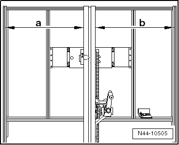
- Dimension -a- = dimension -b-.
-- Position the Setting Device Basic Set :VAS6430/1A at a distance of -a- 150 cm ± 2.5 cm from the center of the wheel hub on the front wheels to the beam on the Setting Device Basic Set :VAS6430/1A , as shown.
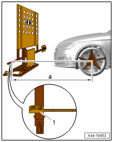
- Measuring tape
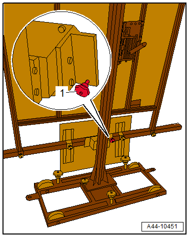
- The :VAS6430/1A must not be moved on the calibration beam.
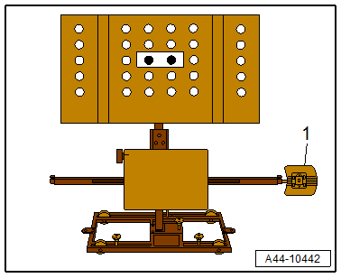
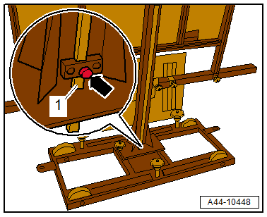
-- Place the :VAS6331/1 -1- for the ACC adjustment on the :VAS6430 on the right side and tighten.
- The alignment stand must be in the lowest level position for the next step.
-- Enter the height value -A- between the :VAS6430/1A contact patch and the wheel contact surface as shown in the illustration and enter it in the alignment computer.
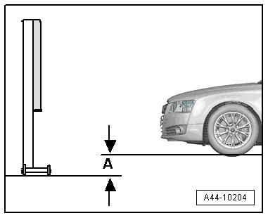
Height calibration board for all Audi SUV models: 1400 mm + height value -A-.
Height calibration board for all Audi non-SUV models: 1200 mm + height value -A-.
-- Loosen the bolt -arrow- and place the measuring bar -1- on the floor.
-- Adjust the calibration board to the specified height -2- according to the wheel alignment computer using the crank -1-.
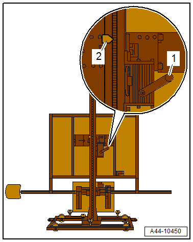
If the specified height was reached -2-, then the measuring bar must be pushed slightly upward and secured with the clamping screw.
- If in later procedures the height of the calibration board must be corrected, make sure the measuring bar is touching the ground when this is being done.
-- Balance the bubble level -A- using the adjusting screw -1-.
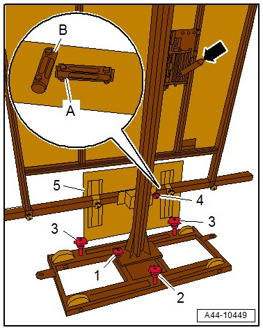
The bubble level adjustment -A- serves to balance the ground conditions.
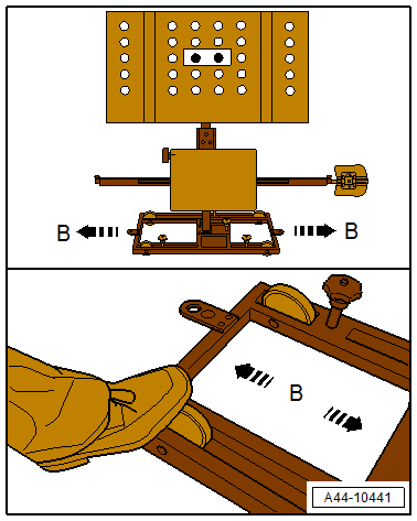
-- Move the :VAS6430/1A at the sides in direction of -arrow B- until the display on the alignment computer is within the tolerance range.
-- Secure the :VAS6430/1A by tightening the bolts -2 and 3- slightly. (This prevents the :VAS6430 from rolling away).
-- Turn the fine adjustment screw -1- until the display on the wheel alignment computer is within the tolerance range.
-- Balance the bubble level -A- using the adjusting screw -1-.
-- Level the bubble level -B- using the adjusting screw -2-.
Because small height changes can result after adjusting the bubble levels, the height of the calibration board must be checked again. Refer to DRIVER ASSISTANCE SYSTEMS FRONT CAMERA, CALIBRATING - Adjust the calibration board to the specified height -2- according to the wheel alignment computer using the crank -1-. .
Perform any subsequent work using the Vehicle Diagnostic Tester.
-- Connect the Vehicle Diagnostic Tester.
-- Switch the ignition on.
-- Select and start the Diagnostic operating mode.
-- Select the Test plan tab.
-- Select the Select individual test button and select the following tree structure consecutively:
- Body
- Electrical system
- 0001 - OBD-capable system
- 00A5 - Driver Assistance Systems Front Camera - R242
- 00A5 - Driver Assistance Systems Front Camera functions
- 00A5 - Calibrate control module
-- Start the selected program and follow the instructions on the Vehicle Diagnostic Tester display.
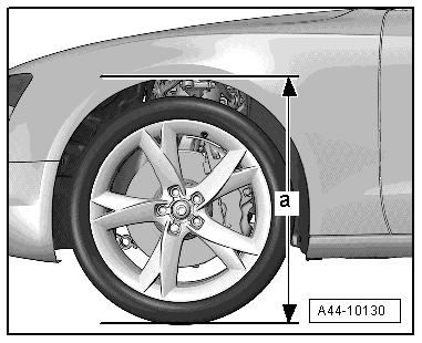
Next, determine the height of the body.
-- Determine the body height -a- at all four wheels in the center of the wheel between the wheel contact surface and the lower edge of the fender or wheel housing.
Additional work, when the Driver Assistance Systems Front Camera -R242- is replaced:
- Adjust the headlamps. Refer to HEADLAMP, ADJUSTING .