Control Module for Emergency Call Module and Communication Unit (1 of 2)
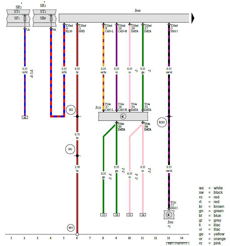
J393 - Comfort System Central Control Module
J533 - Data Bus on Board Diagnostic Interface
J949 - Control Module for Emergency Call Module and Communication Unit
SR1 - Relay and Fuse Panel 1
SF1 - Fuse 1 (On Fuse Panel F)
ST2 - Fuse Panel 2
SR2 - Relay and Fuse Panel 2
ST3 - Fuse Panel 3
SB9 - Fuse 9 (On Fuse Panel B)
T20ad - 20-Pin Connector, Black
T32c - 32-Pin Connector, Black
T54e - 54-Pin Connector, Gray
381 - Ground Connection 16 (in Main Wiring Harness)
382 - Ground Connection 17 (in Main Wiring Harness)
893 - Ground Connection 2 on Left B-Pillar
B281 - Positive Connection 5 (15a) (in Main Wiring Harness)
* - Refer to Applicable Wiring Diagram for Fuse Positions
*2 - Refer to Applicable Convenience System Wiring Diagram
*3 - Ethernet Connection
*4 - From December 2019
*5 - Through November 2019
*6 - For Vehicles with China Equipment
*7 - From December 2021
*8 - For Vehicles with External Vehicle Communication