Peripheral Camera System, Calibrating
-- The vehicle must be on a level surface.
-- Roll out the Calibration System: VAS 721 001 at the left and right near the vehicle.
-- Install the rear and front clamping strips on the Calibration System: VAS 721 001 .
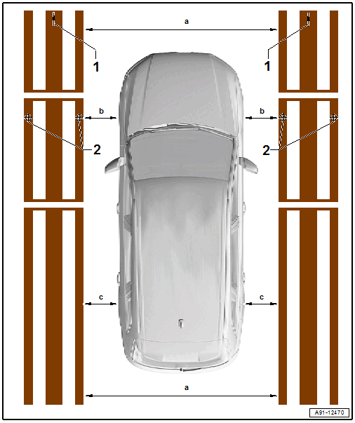
-- Align the crosshairs -2- to the front axle of the vehicle (center front wheel).
-- Align both calibration devices parallel. The vehicle must be located in the center between both calibration devices.
Pay attention to the following measurement requirements:
- Dimension -a- 2000 to 2500 mm ± 5 mm, front and rear the same
- The dimension -b- must be the same on both sides
- The dimension -c- must be the same on both sides
-- Set-up the requirement for the vehicle. Refer to Calibration Requirements on Vehicle .
-- Connect the Vehicle Diagnostic Tester.
Calibrating Procedure
-- Select the Diagnostic mode and start the diagnosis.
-- Select the Test plan tab.
-- Select the Select individual test button and select the following tree structure consecutively:
- Body
- Electrical system
- 01 - OBD-capable systems
- 6C - peripheral camera control module | J928
- 6C - peripheral camera control module, functions
- 6C - Calibration
From here, the Vehicle Diagnostic Tester advances the calibration procedure forward.