Overview - Front Brakes, Steel Brakes 1LA/1LB
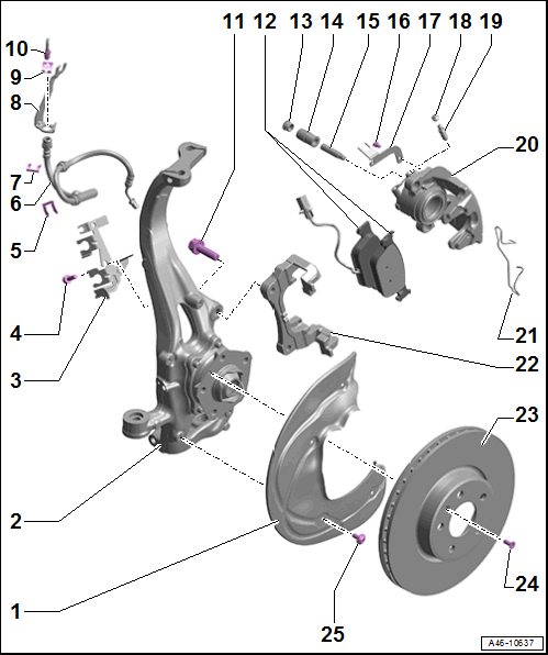
- Brake Shield
- Wheel Bearing Housing
- Bracket
- For brake hose and wire
- Bolt
- 20 Nm
- Replace if damaged
- Replace self-locking bolts and nuts after removing
- Clean before re-using
- Hose Bracket
- For brake hose
- Brake Hose
- Brake hose to brake caliper tightening specification: 14 Nm
- Replace if damaged
- Make sure the brake hose is routed correctly. Make sure the brake hose is not blocked, bent, twisted or rubbing against the vehicle.
- Make sure that tabs are properly seated in the grooves on the bracket.
- Hose Bracket
- For brake hose
- Bracket
- For the brake line/hose
- On the body
- Spring
- Replace if damaged
- Brake Line
- Brake line to brake hose tightening specification: 14 Nm
- Replace a damaged or bent brake line
- Do not change the bending shape.
- Bolt
- 200 Nm
- Replace if damaged
- Clean before re-using
- Replace self-locking bolts and nuts after removing
- Brake Pads
- Always replace on both axles.
- Allocation. Refer to the Parts Information.
- Left inner brake pad with the Left Front Brake Pad Wear Sensor -G34-
- If the brake pad wear indicator wire is damaged, replace the brake pads
- Check the pad thickness. For the wear limit. Refer to BRAKE PADS, CHECKING THICKNESS
- Refer to BRAKE PADS, REMOVING AND INSTALLING, STEEL BRAKES 1LA/1LB
- Refer to Fig 2
- Cap
- Bearing Bushing
- Guide Pin
- 30 Nm
- Refer to BEARING BUSHING AND GUIDE PIN, REPLACING
- Bolt
- 9 Nm
- Replace if damaged
- Replace self-locking bolts and nuts after removing
- Clean before re-using
- Bracket
- For brake hose and wire
- Protective Cap
- Bleed Screw
- 18 Nm
- Refer to HYDRAULIC SYSTEM, BLEEDING
- Before installing, thinly coat with Assembly Paste :G 052 150 A2 .
- Brake Caliper Housing
- Allocation. Refer to the Parts Information.
- To replace brake pads, unfasten from brake carrier
- Refer to BRAKE CALIPER, REMOVING AND INSTALLING, STEEL BRAKES 1LA/1LB
- Refer to BRAKE CALIPER, REPLACING, STEEL BRAKES 1LA/1LB
- Servicing. Refer to BRAKE CALIPER PISTON, REMOVING AND INSTALLING, SINGLE-PISTON BRAKE .
- Spring
- Insert in both holes on the brake caliper housing
- The spring must be pressed under brake carrier after it is inserted in both holes. If improperly installed, the wear of the outer brake pad cannot be adjusted, thereby increasing brake pedal travel.
- Insert in both holes on the brake caliper housing
- Brake Carrier
- Refer to BRAKE CARRIER, REMOVING AND INSTALLING
- Remove and install together with the brake caliper. Refer to BRAKE CALIPER, REMOVING AND INSTALLING, STEEL BRAKES 1LA/1LB .
- Brake Rotor
- Allocation. Refer to the Parts Information.
- Wear limit. Refer to TECHNICAL DATA, BRAKES .
- Maximum lateral run-out: 0.06 mm
- If the brake rotor is installed, measure using the Dial Indicator - 0-10mm :VAS6079 and Dial Indicator Bracket :6079/1 .
- Clean away any dirt and rust on the brake rotor, and perform the measurement 10 mm from the outer edge of the brake rotor.
- Do not use excessive force to separate the brake rotor from the wheel hub. Use rust remover, if necessary, otherwise the brake rotor could be damaged.
- Refer to BRAKE ROTOR, REMOVING AND INSTALLING, STEEL BRAKES CAUTION:
Risk of accident due to uneven braking.
- If a brake rotor is damaged or worn, check the other brake rotors for damage and wear.
- Bolt
- 8 Nm
- Replace if damaged
- Replace self-locking bolts and nuts after removing
- Clean before re-using
- Bolt
- 10 Nm
- Replace if damaged
- Replace self-locking bolts and nuts after removing
- Clean before re-using
Brake Pad Installation Position, Steel Brakes 1LA/1LB
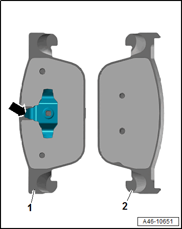
- Clip the inner brake pad with the spring -arrow- into the brake caliper piston
- Engage the outer brake pad into the brake carrier