SUBFRAME, Securing: Procedure
There is a risk of an accident due to an unsecured engine/transmission subassembly!
- The engine must be supported in the installation position for the following steps.
-- Support the engine in the installation position. Refer to SUBFRAME MOUNT .
-- Remove the front wheels. Refer to WHEELS AND TIRES .
-- Remove the noise insulation. Refer to NOISE INSULATION, REMOVING AND INSTALLING .
-- Remove the left and right wheel spoiler. Refer to FRONT WHEEL SPOILER, REMOVING AND INSTALLING .
-- A5 Cabriolet: remove the diagonal braces. Refer to the appropriate service information .
-- Remove the clip nuts from the crossbrace.
-- Position the :T10552 with the :VAS6931 under the subframe and lift.
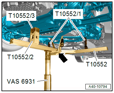
-- Bring the :T10552/2 with the :T40386 all the way onto the front crossbrace.
-- Place the :T10552/1 all the way into the rear holes on the crossbrace by turning left and right at the threaded sleeve.
-- Secure the crossbrace with a tensioning strap -arrow-.
There is a risk of damaging the threads on the subframe threaded connection to the body.
- The subframe bolts on the body must not be loosened or tightened with an impact wrench.
- Always install all bolts by hand for the first few turns.
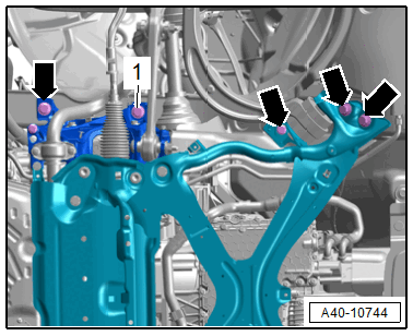
To secure the subframe, a :T40327 must be installed at position -1- on the left and right side.
The locating pins must only be tightened to a maximum of 20 Nm or else the locating pin bolts will be damaged.
Due to the ribbed washers for the bolts, the holes for the subframe are slightly peened. They must be deburred if necessary.
-- Replace the bolts -1- on both sides of the vehicle with the :T40327 and tighten to 20 Nm.
- The suspension is now secured.
-- Remove the bolts on the left and right side -arrows-.
Remove the :T40327
Removal is performed in the reverse order. Note The Following :
-- Remove the locating pins and tighten a new bolt at this position.
There is a risk of damaging the threads on the subframe threaded connection to the body.
- The subframe bolts on the body must not be loosened or tightened with an impact wrench.
- Always install all bolts by hand for the first few turns.
Risk of accident!
- If the vehicle will be driving on the streets, all bolts and nuts must be tightened properly according to the guidelines.
-- Remove the :10-222A . Refer to SUBFRAME MOUNT .
-- A ROAD TEST MUST BE PERFORMED AFTER COMPLETING REPAIRS. IF THE STEERING WHEEL IS CROOKED, THE WHEELS MUST BE ALIGNED. Refer to AXLE ALIGNMENT .