SUBFRAME With Steering Gear, Removing And Installing: Removing
During installation, all cable ties must be installed at the same location.
-- Before starting the procedure, determine the curb weight position. Refer to WHEEL BEARING IN CURB WEIGHT POSITION, LIFTING VEHICLES WITH COIL SPRING .
-- Secure the subframe. Refer to SUBFRAME, SECURING .
-- Disconnect the connector -2- and free up the wire.
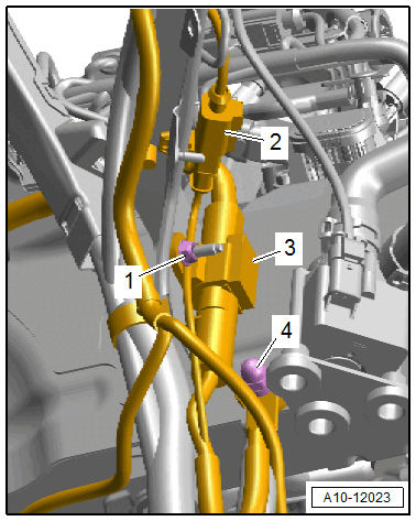
-- Loosen the nut -1- several turns, and free up and disconnect the connector -3-.
-- Remove the nut -4- and free up the ground wire.
-- Free up the wires to the steering gear.
-- Equipment versions with electro-hydraulic engine mount: Disconnect the left and right connector -2- for the electrohydraulic engine mount solenoid valve.
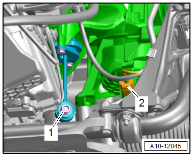
-- Equipment versions with support bearing: Remove the left and right bolt -1- for the support bearing.
The illustration shows the installation position on a vehicle with a 2.0L TFSI engine.
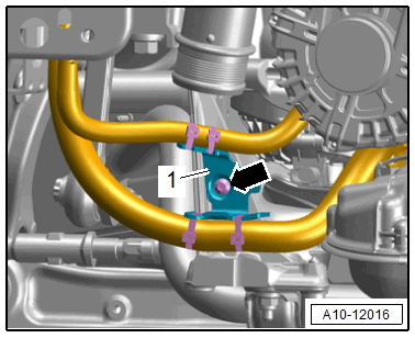
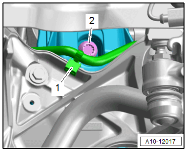
-- Remove the bolt -arrow- and free up the bracket -1- with the wiring harness.
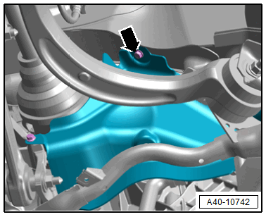
-- Remove the left and right bolts -arrow- for the subframe shield.
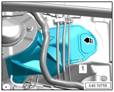
-- Open the left and right cover -1- on the suspension strut tower in direction of -arrow-.
There is a risk of damaging the joints on the upper control arm.
- The wheel bearing housing must be supported.
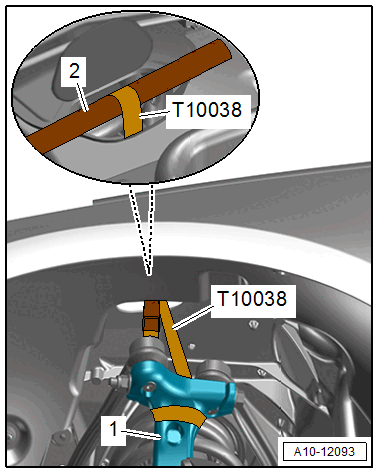
-- Tie up the left and right wheel bearing housing -1- as shown with the :T10038 . Use a hammer handle -2- to do this.
-- To protect the threads, remove the nut -arrow- on the left and right side from the tie rod end joint pin until it is flush with the joint pin threads.
There is a risk of injury from falling components.
- When pressing off, the tie rod end loosens abruptly from the wheel bearing housing. Use, for example, the :VAS6931 to secure.
There is a risk of damaging the ball joint puller.
- Make sure that both puller lever arms are parallel to each other when using maximum force.
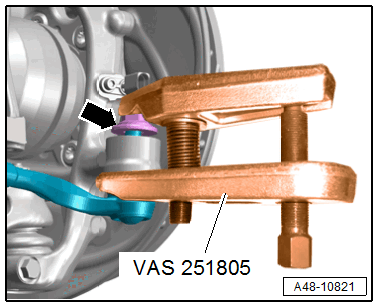
-- Remove the left and right tie rod end with the :VAS251805 from the wheel bearing housing.
-- Then remove the nut. Use a 6 mm inner hex socket to counterhold at the joint pin if necessary.
Equipment Versions with Electronic Damping
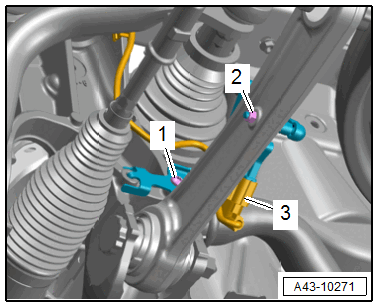
-- Disconnect the left and right connector -3- for the level control system sensor and free up the wire.
-- Remove the nut -2- and free up the coupling rod.
Ignore item -1-.
Continuation for All Vehicles
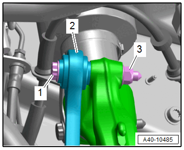
-- Disconnect the left and right control arm threaded connections -1 and 3-.
-- Pivot the control arm toward the front.
To remove the bolt -1 -, push the steering all the way to the left or right.
Ignore item -2-.
-- To protect the threads, remove the nut -arrow- on the left and right from the guide link joint pin just until it is flush with the joint pin threads.
There is a risk of injury from falling components.
- When pressing off, the tie rod end loosens abruptly from the wheel bearing housing. Use, for example, the :VAS6931 to secure.
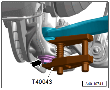
-- Press out the guide link joint pin with the :T40043 from the conical seat. Do not damage the CV boot while doing so.
-- Remove the nut and free up the guide link on the wheel bearing housing. If necessary, counterhold the joint pin with a TORX® 40 socket to do this.
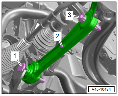
-- Remove the left and right nut -3- and the bolt -1- for the coupling rod -2-.
-- Remove the steering intermediate shaft from the steering gear and then push together. Refer to STEERING INTERMEDIATE SHAFT, REMOVING AND INSTALLING .
-- Remove the left and right drive axle from the transmission. Refer to DRIVE AXLE, REMOVING AND INSTALLING .
-- Equipment versions with SCR system: Free up the SCR delivery line -1- on the subframe.
-- Remove the left and right bolt -2- and lower the subframe with the :VAS6931 .
Make sure there is enough clearance for the wires when lowering the subframe.