Control Arm, Removing And Installing: Removing
-- Before starting the procedure, determine the curb weight position. Refer to WHEEL BEARING IN CURB WEIGHT POSITION, LIFTING VEHICLES WITH COIL SPRING .
-- Remove the front wheel. Refer to WHEELS AND TIRES .
-- Remove the noise insulation. Refer to NOISE INSULATION, REMOVING AND INSTALLING .
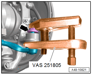
-- To protect the threads, remove the nut -arrow- from the tie rod end joint pin until it is flush with the joint pin threads.
There is a risk of injury from falling components.
- When pressing off, the tie rod end loosens abruptly from the wheel bearing housing. Use, for example, the :VAS6931 to secure.
There is a risk of damaging the ball joint puller.
- Make sure that both puller lever arms are parallel to each other when using maximum force.
-- Remove the tie rod end with the :VAS251805 from the wheel bearing housing.
-- Then remove the nut. Use a 6 mm inner hex socket to counterhold at the joint pin if necessary.
-- Tie up the tie rod.
To prevent the joints on the upper control arm from being damaged, support the wheel bearing housing against too strong rebound.
-- Turn the wheel hub, until a wheel bolt hole is at the top.
-- Install the :T10149 with a wheel bolt -2- on the wheel hub.
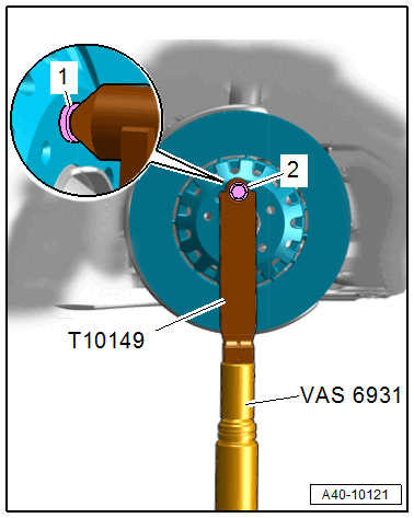
Ignore item -1-.
-- Support the wheel bearing housing over the :T10149 using the :VAS6931 .
Risk of accident!
- Do not lift or lower the vehicle when the :VAS6931 is under the vehicle.
- Do not leave the :VAS6931 under the vehicle any longer than necessary.
-- Equipped on some models: Remove the nut -2- and free up the coupling rod for the level control system sensor.
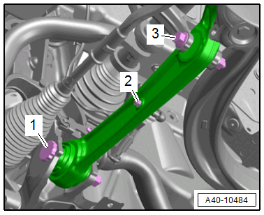
-- Disconnect the threaded connections -1 and 3- for the control arm.
-- Pivot the control arm toward the front.
To remove the bolt -1-, push the steering all the way to the left or right.
-- Remove the bolt -2-.
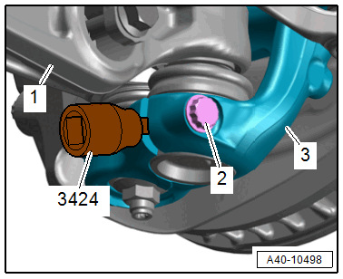
-- Insert the :3424 into the slit on the wheel bearing housing -3- and turn 90°.
-- Remove the control arm -1- with the ball joint.