Upper Transverse Link
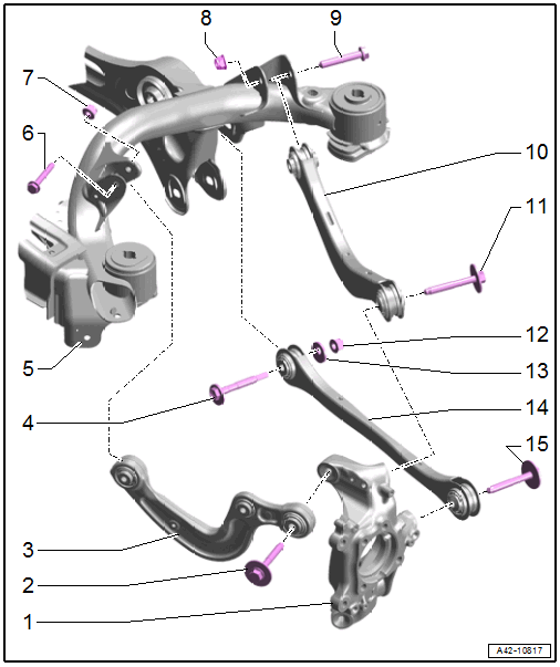
- Wheel Bearing Housing
- Bolt
- 70 Nm + 180°
- Always replace after removing
- Front Upper Transverse Link
- Removing and installing. Refer to FRONT UPPER TRANSVERSE LINK, REMOVING AND INSTALLING .
- Installation position. Refer to Fig 2.
- Eccentric Bolt
- Subframe
- Bolt
- 40 Nm + 180°
- Always replace after removing
- Tighten in the curb weight position. Refer to WHEEL BEARING IN CURB WEIGHT POSITION, LIFTING VEHICLES WITH COIL SPRING .
- Nut
- Always replace after removing
- Nut
- Always replace after removing
- Bolt
- 70 Nm + 180°
- Always replace after removing
- Tighten in the curb weight position. Refer to WHEEL BEARING IN CURB WEIGHT POSITION, LIFTING VEHICLES WITH COIL SPRING .
- Rear Upper Transverse Link
- Removing and installing. Refer to REAR UPPER TRANSVERSE LINK, REMOVING AND INSTALLING .
- Installation position. Refer to Fig 2.
- Bolt
- 70 Nm + 180°
- Always replace after removing
- Tighten in the curb weight position. Refer to WHEEL BEARING IN CURB WEIGHT POSITION, LIFTING VEHICLES WITH COIL SPRING .
- Nut
- 90 Nm
- Always replace after removing
- Loosen and tighten using the 21 mm internal multi-point socket
- Tighten in the curb weight position. Refer to WHEEL BEARING IN CURB WEIGHT POSITION, LIFTING VEHICLES WITH COIL SPRING .
- Eccentric Washer
- Tie Rod
- Removing and installing. Refer to TIE ROD, REMOVING AND INSTALLING .
- Installation position. Refer to Fig 2.
- Bolt
- 70 Nm + 180°
- Always replace after removing
- Tighten in the curb weight position. Refer to WHEEL BEARING IN CURB WEIGHT POSITION, LIFTING VEHICLES WITH COIL SPRING .
Transverse Link and Tie Rod Installation Position
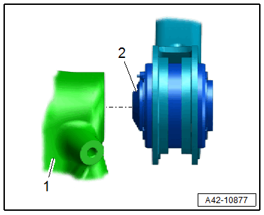
- The ball side -2- on the transverse link or tie rod must engage in the wheel bearing housing -1-.