Spring, Removing And Installing: Installing
Install in reverse order of removal and note the following:
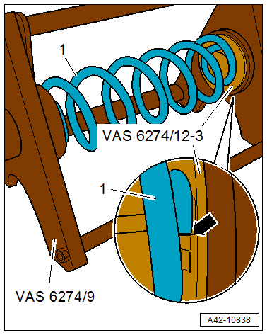
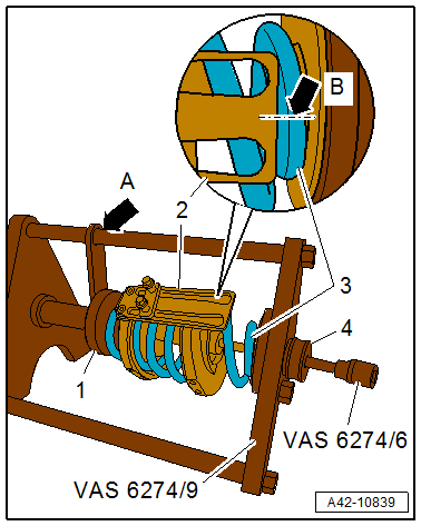
-- Insert the coil spring -1- into the :VAS6274/9 .
- The end of the spring coil on the bottom of the coil spring must rest against -arrow- the :VAS6274/12-3
-- Insert the :VAS6274/12-2 as shown into the coil spring -2-.
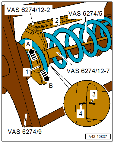
-- Press the locking plate -1- outward in the direction of the -arrow B- (open).
-- Insert the :VAS6274/12-7 with the :VAS6274/5 into the thrust plate and turn 90° until the line marking -4- on the thrust plate is flush with the line marking -3- on the plunger.
-- Pull the plunger into the thrust plate and secure with the locking plate in the direction of the -arrow A- (close).
-- Remove the :VAS6274/5 .
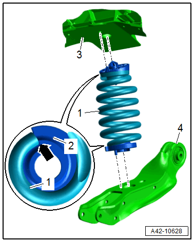
-- Insert the :VAS6274/12-1 into the coil spring -1-.
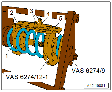
- When removing, note the marks applied for the installation position and the locking device bracket positions -2 and 5- to the thrust plates for the corresponding side of the vehicle.
-- Tighten the locking device bolts -3- to the backing plate -4- by hand.
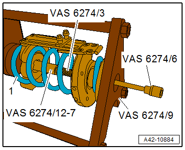
-- Insert the :VAS6274/3 loosely into the :VAS6274/12-7 using the :VAS6274/6 . Tension the coil spring -1- slightly using the :VAS6274/9 while doing so.
-- Insert the 130 mm long centering sleeve -4- all the way.
-- Align the locking device -2- to the mark applied during removal -arrow B- on the coil spring -3-.
-- Tension the coil spring using the :VAS6274/6 and at the same time using the :VAS6274/9 up to the previously applied mark -arrow A-.
-- Make sure when tensioning that the centering sleeve does not slide off of the spindle. Push back if necessary.
If necessary, the thrust plates must be held in position up to the mark -arrow B- using the :VAS6274/7 .
There is a risk of damaging the threads.
- The :VAS6274/3 must not be tensioned or released using an impact wrench.
- Always turn the spindle using a commercially available ratchet.
-- Continue to tension the coil spring using the :VAS6274/6 until the coil spring rests loosely on the hydraulic tensioner.
-- Release the tension on the hydraulic tensioner, and remove the centering sleeve and the pretensioned coil spring.
- :VAS6274/8 fixed with : VAS6274/12-5 .
-- Bring the coil spring and the spring plate into the installation position. Refer to Figure.
There is a risk of damaging the threads.
- The :VAS6274/3 must not be tensioned or released using an impact wrench.
- Always turn the spindle using a commercially available ratchet.
-- Release the tension on the coil spring with the :VAS6274/6 . Do so by counterholding with the :VAS6274/7 .
There is a risk of damaging the transverse link.
- The tensioner thrust plates must not contact the transverse link when releasing the tension on the coil springs. Turn the thrust plates if necessary.
- Overview table for when an axle alignment is needed. Refer to NEED FOR AXLE ALIGNMENT, EVALUATING .