Installing right high pressure pump
NOTE:
RISK OF DAMAGE
Contaminant or foreign body.
Contamination can result in malfunctions, loss of function or leaks.
Contaminant or foreign body.
Contamination can result in malfunctions, loss of function or leaks.
- Adhere to the utmost cleanliness.
- Protect components from contamination e.g. by covering.
- Close off line connections with seal plugs.
NOTE:
TECHNICAL INFORMATION
The high pressure pump is preloaded by the piston spring and must be removed by alternately unscrewing the screws without tilting.
Before installing the high pressure pump, the cam of the high pressure pump drive must be turned to bottom dead center.
If necessary, turn the engine in the direction of engine rotation on the central bolt of the crankshaft, otherwise there is a risk of piston breakage of the high pressure pump.
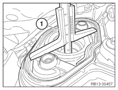
- Place the depth gauge (1) flat onto the high pressure pump flange.
- Turn the engine at the central bolt in the direction of the engine rotation until the depth gauge (1) shows that the camshaft has reached the BDC position.
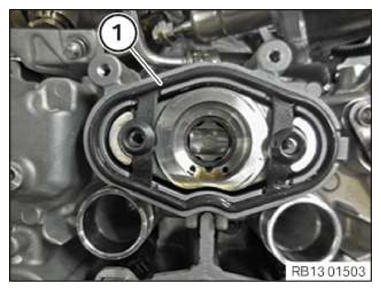
- Replace gasket (1).
Parts: Gasket
- Replace screws (1).
Parts: screw
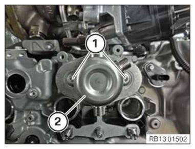
- Install the high pressure pump (2).
- Position the screw (1) on the high pressure pump (2) and tighten in alternating order in steps of 90° each.
TIGHTENING TORQUES SPECIFICATION
| High-pressure pump to cylinder head | ||
| M6x20 Replace screws. Tighten the screws evenly to the tightening torque in 90° steps. |
Tightening torque | 12 Nm |
Follow-up work
- Refer to MOUNT THE FUEL SUPPLY LINE .
- Refer to INSTALL THE RIGHT HIGH-PRESSURE RAIL .
- Refer to INSTALLING THE SOUND INSULATION ON THE RIGHT-HAND CYLINDER HEAD COVER .
- Refer to SECURE THE WIRING HARNESS ON THE CYLINDER HEAD COVER ON THE RIGHT .
- Refer to INSTALLING THE HOLDER FOR THE DIGITAL MOTOR ELECTRONICS CONTROL UNIT ON THE RIGHT .
- Refer to INSTALL THE INTEGRATED POWER SUPPLY MODULE (PDM) .
- Refer to INSTALLING THE DME CONTROL UNIT FOR CYLINDERS 1 TO 4 .
- Refer to CHECK THE COOLANT LEVEL IN THE LOW-TEMPERATURE COOLANT CIRCUIT AND TOP UP, IF NEEDED .
- Refer to INSTALL REAR UNDERBODY PROTECTION .
- Refer to INSTALL RIGHT CLEAN AIR PIPE .
- Refer to CONNECTING THE RIGHT CHARGE AIR LINE TO THE EXHAUST TURBOCHARGER
- Refer to INSTALLING THE RIGHT UNFILTERED-AIR DUCT .
- Refer to INSTALLING ALL IGNITION COILS ON THE RIGHT .
- Refer to INSTALLING INTAKE FILTER HOUSING .
- Refer to INSTALL ACOUSTIC COVER .
- Refer to INSTALL THE REAR TOP CROSS CONNECTION .
- Refer to INSTALL FRONT CROSS CONNECTION .
- Refer to INSTALLING FRONT-END STRUT ON LEFT AND RIGHT .
- Refer to INSTALLING THE COVER ON THE LEFT AND RIGHT IN THE ENGINE COMPARTMENT AT THE TOP
- Refer to DISCONNECTING ALL BATTERY GROUND LEADS .