Installing automatic transmission (all-wheel drive vehicle) (GA8HP75Z)
NOTE:
RISK OF DAMAGE
Damage to the transmission.
Damage to the transmission due to unapproved transmission oil.
Damage to the transmission.
Damage to the transmission due to unapproved transmission oil.
- Use only the approved TRANSMISSION OIL .
- Check the transmission OIL LEVEL after completing the repair.
NOTE:
TECHNICAL INFORMATION
After completion of the work, program the control unit for the electronic gearbox control (EGS).
After completion of the work, program the control unit for the electronic gearbox control (EGS).
Checking installation position of torque converter
NOTE:
RISK OF DAMAGE
Damage to the automatic transmission/impeller.
When disconnecting the engine and transmission, the torque converter can become loose! Failure to observe the correct installation positions of the torque converter may lead to damage to the impeller driver.
Damage to the automatic transmission/impeller.
When disconnecting the engine and transmission, the torque converter can become loose! Failure to observe the correct installation positions of the torque converter may lead to damage to the impeller driver.
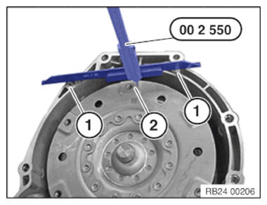
- Make sure that the torque converter is in the correct installation position before installing the automatic transmission.
- Check the installation dimension between the contact surfaces (1) and the outer edge (2) of the threaded hole of the torque converter with the special tool 0 490 189 (00 2 550) .
- See REPAIR INSTRUCTIONS - Removing and installing/replacing torque converter
NOTE:
RISK OF DAMAGE
Damage of the flywheel and automatic transmission.
A non-horizontal fit during the removal and installation of the automatic transmission can lead to damage on the automatic transmission or flywheel.
Damage of the flywheel and automatic transmission.
A non-horizontal fit during the removal and installation of the automatic transmission can lead to damage on the automatic transmission or flywheel.
- Align the automatic transmission completely horizontal to the engine during the removal and installation.
- Check for correct alignment before tightening the transmission bolts.
- Before installing the automatic transmission, horizontally align it to the engine.
Checking lining sleeves
- Check the fitting sleeves (1) for correct seating and damage and replace if necessary.
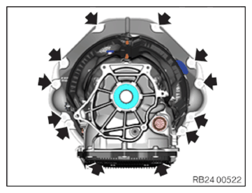
Flange-mount transmission
- Transmission flange-mount.
- Rotate torque converter until bore in torque converter is flush with bore in drive plate.
- Join and tighten the transmission bolts (arrows).TIGHTENING TORQUES SPECIFICATION
Transmission to engine M8 Tightening torque 19 Nm M10 Tightening torque 38 Nm Remove the special tool from the torque converter
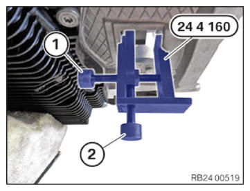
- Release the screws (1) and (2).
- Remove the special tool 0 494 451 (24 4 160)
.
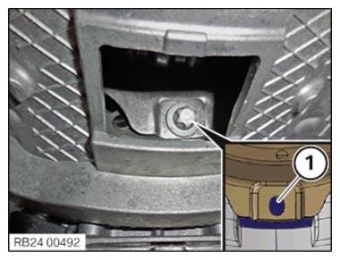
Tighten converter bolt
- Replace screws.
Parts: screw
- First
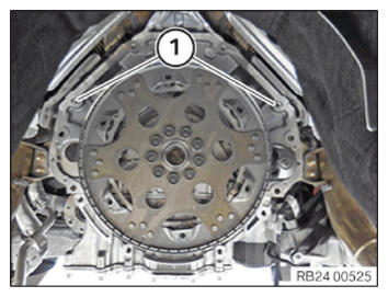
screw the torque converter onto the vertically arranged elongated hole (1).
It is compulsory to screw the torque converter onto the vertically arranged elongated hole (1) first.
- Rotate the torque converter until the elongated hole (1) is visible in the opening.
- Tighten down screw.TIGHTENING TORQUES SPECIFICATION
Torque converter to flywheel M10
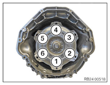
Replace screws.Tightening torque 60 Nm - Observe the tightening sequence of the additional five screws (torque converter on flywheel) compulsorily:
Tightening sequence: 1-4-3-6-5-2
The screw connection (1) is the vertically arranged elongated hole in the torque converter.
 Courtesy of BMW OF NORTH AMERICA, INC.TIGHTENING TORQUES SPECIFICATION
Torque converter to flywheel M10
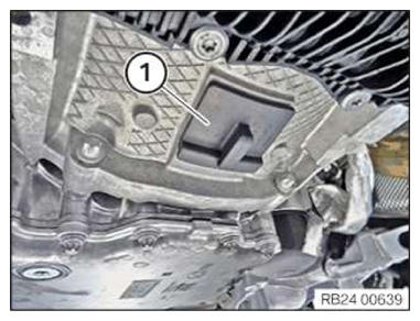
Replace screws.Tightening torque 60 Nm - Install the sealing cap (1).
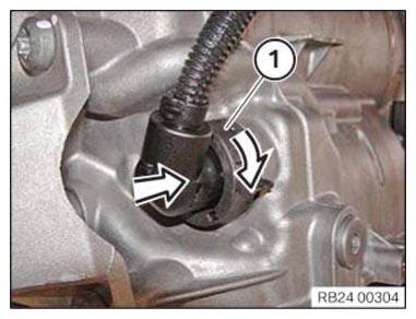
Lock the connector with the sealing sleeve
- Remove the special tool 0 494 213 (24 2 390)
in arrow direction from the sealing sleeve.NOTE: TECHNICAL INFORMATION
Notes on mechatronics are a fundamental requirement for these repair instructions and must be complied with at all times.
For ADDITIONAL INFORMATION see: 24 34... Notes on mechatronics (GA8HP50Z/GA8HP51Z/GA8HP75Z/GA8***H - Slide the connector (1) on and turn it to lock.

Notes on mechatronics
CAUTION:
Materials harmful to health.
Contact with fluids harmful to health!
Contact with fluids harmful to health!
- Note and follow safety instructions on containers.
- Conduct all work in appropriate personal protective equipment only.
NOTE:
RISK OF DAMAGE
Damage to the automatic transmission after removal of the mechatronics.
Serious damage to the automatic transmission due to non-compliance with the following tasks:
Damage to the automatic transmission after removal of the mechatronics.
Serious damage to the automatic transmission due to non-compliance with the following tasks:
- Load specific data status with the diagnostic system using an appropriate scan tool.
- Use only approved TRANSMISSION OIL .
- After completion of repair work, check the transmission OIL LEVEL .
NOTE:
RISK OF DAMAGE
Electrostatic discharge.
Damage to or destruction of electrical components.
Electrostatic discharge.
Damage to or destruction of electrical components.
- Leave the electrical components in their original packaging until they are being installed. Only use the original packaging for returning the product. Always package removed components straight away.
- Read and comply with user information on using the associated special tool 12 7 060.
- Only tap the housings of electrical components. Do not tap pins or multi-pin connectors directly.
- Wear electrically conductive clothing and antistatic shoes (with ESD symbol).
- For additional information see: 61 35... NOTES on ESD (electrostatic discharge) protection
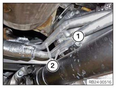
Fix hydraulic lines
- Replace sealing rings.
Parts: Sealing ring
- Install hydraulic lines (2) on transmission.
- Position and tighten the screw (1).TIGHTENING TORQUES SPECIFICATION
Transmission oil line to transmission M6x25
Replace the sealing ring.Tightening torque 8 Nm - Install hydraulic lines (2) on transmission.
- Position and tighten the screw (1).TIGHTENING TORQUES SPECIFICATION
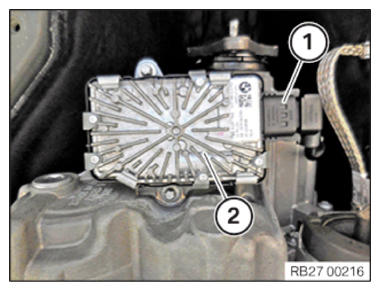
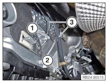
Transmission oil line on holder MVI6 Tightening torque 4 Nm Connecting the connector with the VTG control unit
- Connect the connector (1) to the VTG control unit for the longitudinal torque distribution (2).
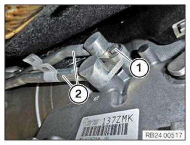
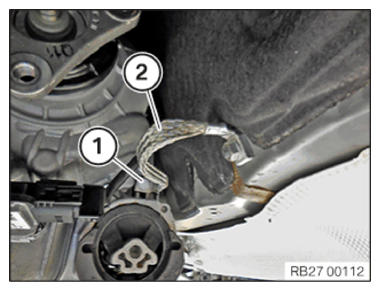
Install the ground strap
- Install the ground strap (2).
- Tighten down screw (1).TIGHTENING TORQUES SPECIFICATION
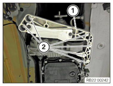
Ground strap to transmission or body M8 Tightening torque 19 Nm Installing transmission cross member.
- Install the transmission cross member.
- Tighten down screws (2).TIGHTENING TORQUES SPECIFICATION
Transmission cross member to body M8 Tightening torque 19 Nm - Tighten down screw (1).TIGHTENING TORQUES SPECIFICATION
Transmission cross member to rubber mounts M12 Tightening torque 68 Nm Securing the lines
- Secure the lines (3).
- Tighten down screw (1).
- Tighten down screw (2).TIGHTENING TORQUES SPECIFICATION
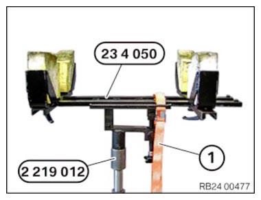
Standard screw connection M5 Tightening torque 5 Nm Remove the transmission jack
- Release the luggage strap (1) from the transmission.
- Remove the special tools 0 495 498 (23 4 050) and 2 219 012 from the transmission.
Follow-up work
- Install the front axle transmission front PROPELLER SHAFT .
- Fasten the (partially removed) PROP SHAFT
- Install the RETAINING PLATES .
- Install the HEAT SHIELDS .
- If installed: install the right and left TORSION STRUT where required.
- Install the tunnel connecting SUPPORTS .
- Install the THRUST FIELD .
- Reconnect all battery GROUND LEADS .
- Check/top up the automatic transmission OIL LEVEL .
- Install the front UNDERBODY PROTECTION/FRONT THRUST FIELD .
- Install the transmission side UNDERBODY PLANKING .
- Install rear UNDERBODY PROTECTION .