Fastening the prop shaft (partially removed)
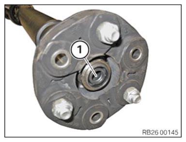
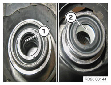
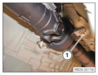
- Check centering (1) for damage; replace if necessary.
- Apply a thin coat of grease to the soft centering (1), if necessary.
The hard centering (2) must not be greased.
CONSUMABLE SPECIFICATIONS
| Lubricating grease Olistamoly 2 LN 584 LO |
100 g, Tube | 83 19 0 447 919 |
- Replace the screws and the self-locking nuts.
Parts: Screws, self-locking nuts
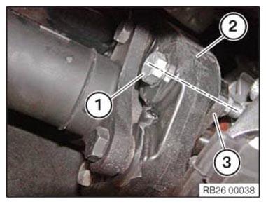
- Assemble the screw connections (1) of the flexible disc (2) and the three-hole flange (3) according to the self-affixed identification.
This should prevent a humming noise from the drive train during driving.
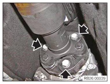
- Hand-tighten screws and nuts (arrows), but do not tighten fully.
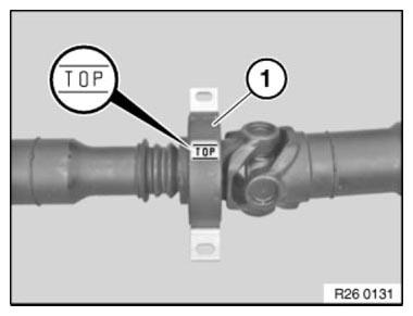
- Install central mount (1) into the transmission tunnel with the designation TOP facing upwards.
- Position central mount.
- Hand-tighten the bolts (1), but do not tighten fully.
- Replace screws.
Parts: Screws
- Counter-hold the screws of the flexible disc on the nut and tighten with the screws.
TIGHTENING TORQUE SPECIFICATIONS
| Front flexible disc to prop shaft | ||
| M12 Replace screws. Jointing torque and angle rotation must be adhered to. Tightening via screw. |
Joining torque | 55 Nm |
| Angle of rotation | 90° | |
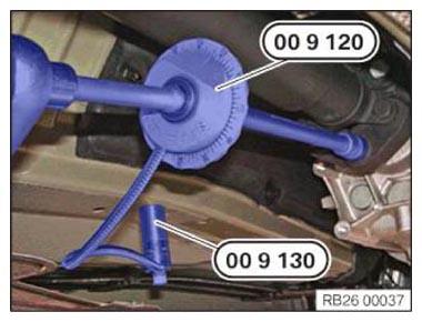
- Secure the special tool 0 490 504 (00 9 120) with the special tool 0 495 108 (00 9 130) on the vehicle underbody and continue to screw it in according to the angle of rotation.
- Tighten down screws (1).
TIGHTENING TORQUE SPECIFICATIONS
| Central mount to body | ||
| M8 | Tightening torque | 19 Nm |