Installing the mechatronics
NOTE:
RISK OF DAMAGE
Damage to the automatic transmission after removal of the mechatronics.
Serious damage to the automatic transmission due to non-compliance with the following tasks:
Damage to the automatic transmission after removal of the mechatronics.
Serious damage to the automatic transmission due to non-compliance with the following tasks:
- Load specific data status with the diagnostic system using an appropriate scan tool.
- Use only approved TRANSMISSION OIL .
- After completion of repair work, check the transmission OIL LEVEL .
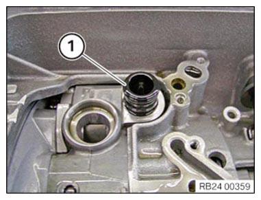
- Replace pressure pipe.
Parts: Pressure pipe
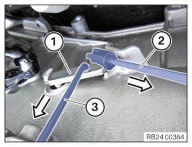
- Install pressure pipe (1).
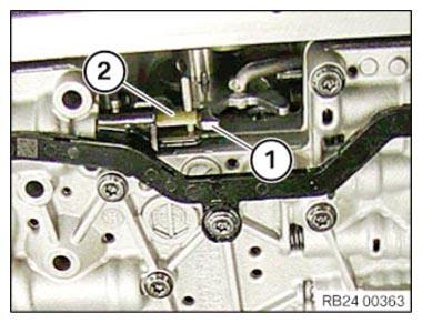
- Fit mechatronics unit.
- Feed shifting claw (1) into gearshift shaft (2).
- Install mechatronics.
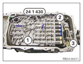
- Tighten wing nuts (1) of the special tool 0 496 715 (24 1 430)
alternately until the mechatronics is applied to the transmission.
- Position the screws (1) and slightly tighten.
- Pull the selector shaft tappet (1) downward with the special tool 2 355 850 (3) in the arrow direction.
- Remove the special tool 2 355 850
(2) in the direction of the arrow.NOTE: TECHNICAL INFORMATION
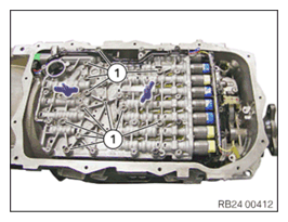
Note the original installation position of the output RPM sensor.
Observe the correct installation position when installing the output RPM sensor.NOTE: TECHNICAL INFORMATION
The tappet on the output RPM sensor may break off during removal or installation. - Attach output RPM sensor (3) carefully and slide onto the stop.
- Position the screws (2) and slightly tighten.
- Loosen wing nuts.
- Remove special tool 0 496 715 (24 1 430) .
- Position the screws (1) and slightly tighten.
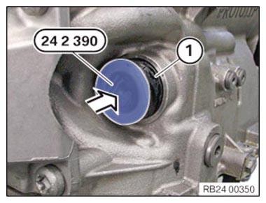
- Replace the sealing sleeve (1).
Parts: Sealing sleeve
- Carefully insert the sealing sleeve (1).
The lug must be in the inner surface.
- Twist the sealing sleeve (1) until the lug has been inserted into the groove of the gear.
- Slide in sealing sleeve (1) up to the stop.
The lug on the sealing sleeve must not be damaged!
- Remove special tool 0 494 213 (24 2 390)
.
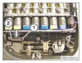
- Lock the sealing sleeve with the slide (2).
- Position the screw (1) and slightly tighten.
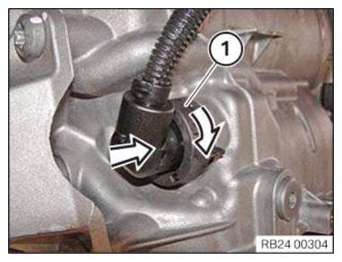
- Insert the connector (1) in the direction of arrow.
- Lock the connector (1) by turning the direction of arrow.
- Replace screws.
Parts: screw
NOTE: TECHNICAL INFORMATION
When assembling, it is essential to observe screwing sequences and tightening torques.
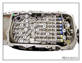
Non-compliance with the regulations can lead to damage. - Tighten screws in the order (1) to (17).
TIGHTENING TORQUES SPECIFICATION
| Mechatronics to transmission | ||
|---|---|---|
| M6x59, M6x20 Replace screws. |
Tightening torque | 8 Nm |
TIGHTENING TORQUES SPECIFICATION
| Output RPM sensor to transmission (position 17) | ||
|---|---|---|
| M6x20 Replace screw. |
Joining torque | 4 Nm |
| Angle of rotation | 12° | |
Follow-up work
- Install the oil volume RESERVOIR (GA8HP50Z, GA8HP51Z, GA8HP75Z, GA8HP76Z, GA8HP95Z).
- Install the transmission OIL PAN (all-wheel drive vehicle) (GA8HP75Z, GA8HP76Z, GA8HP95Z).
- Check/top up the automatic transmission OIL LEVEL .
- Install rear UNDERBODY PROTECTION .
- Install the transmission side UNDERBODY PLANKING .
- Reconnect all battery GROUND LEADS .
- Activate the 48 v ELECTRICAL SYSTEM .