Closing locking ring (vehicles with stationary heating system)
WARNING:
Working on fuel system.
Risk of fire! Danger of explosion!
Risk of fire! Danger of explosion!
- When working on the fuel system, make sure the workstation has sufficient ventilation, e.g., by means of extraction.
- Tightly seal off open lines and connections; collect any leakage fuel directly at the point of exit.
- No fire, sparks, open flames or smoking.
NOTE:
TECHNICAL INFORMATION
Collect and dispose of emerging fluids. Observe country-specific waste disposal regulations.
Collect and dispose of emerging fluids. Observe country-specific waste disposal regulations.
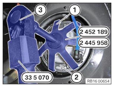
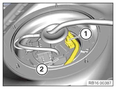
- Place special tool 2 452 189 or 2 445 958 (1) on the locking ring (2).
- Connect the special tool 0 495 554 (33 5 070) with a reversible 1/2 inch (3) ratchet head and place on the special tool 2 452 189 2 445 958 .
- Tighten locking ring (2) in clockwise direction.
- Make sure that the locking ring to the fuel tank is engaged correctly.
Check
- Attach the connector housing to the pump.
NOTE:
TECHNICAL INFORMATION
For vehicles up to 03/2017, it may be necessary to replace the connector on the wiring harness and the pin assignment when exchanging the electric fuel pump.
For vehicles up to 03/2017, it may be necessary to replace the connector on the wiring harness and the pin assignment when exchanging the electric fuel pump.
Result
» The connector does not fit or it cannot be attached!
Measure
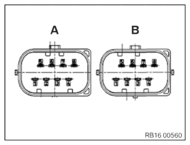
- Replace the 8-pin connector (see applicable BMW parts catalogue) and change the pin assignment (pin 7 and pin 8)!
- Current pin assignment (Connector A)
| Pin | Description | Cable color |
|---|---|---|
| 1 | Lever sensor, left | Green |
| 2 | not used | - - |
| 3 | Ground, lever sensor | Yellow/Blue |
| 4 | Lever sensor, right | Yellow/White |
| 5 | EKP A | Blue |
| 6 | EKB B | Brown |
| 7 | EKP C | Shielding |
| 8 | Ground TEE | Black |
NEW PIN ASSIGNMENT (CONNECTOR B) DESCRIPTION
| Pin | Description | Cable color |
|---|---|---|
| 1 | Lever sensor, left | Green |
| 2 | not used | - - |
| 3 | Ground, lever sensor | Yellow/Blue |
| 4 | Lever sensor, right | Yellow/White |
| 5 | EKP A | Blue |
| 6 | EKP B | Brown |
| 7 | Ground TEE | Black |
| 8 | EKP C | Shielding |
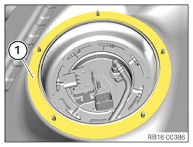
- Position all snap fasteners (1) and lock.
- Connect the plug connection (2).
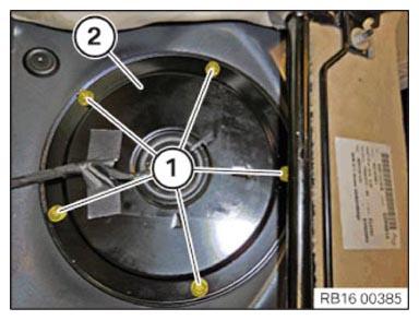
- Replace gasket (1).
Parts: Gasket
- Mount cover (2).
The arrow must point in the direction of travel.
- Replace plastic nuts.
Parts: Plastic nuts
- Insert plastic nuts (1) and tighten.TIGHTENING TORQUES SPECIFICATION
Cover of sensor opening on body Replace plastic nut. tightening torque
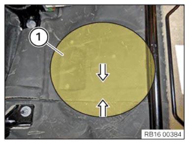
3 Nm - Close the floor trims in the area (1) in arrow direction.