Installing cylinder head cover
Bolts of the cylinder head cover
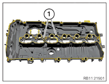
1 Bolts of the cylinder head cover
A - 21 Cylinder head cover
NOTE:
RISK OF DAMAGE
Improper routing of cables and wiring harnesses.
Trapped, crushed or damaged cables may cause short circuits and malfunctions.
Improper routing of cables and wiring harnesses.
Trapped, crushed or damaged cables may cause short circuits and malfunctions.
- Route all cables without abrasions, do not trap and crush.
NOTE:
TECHNICAL INFORMATION
Detents, guides and mounting elements must not be damaged or missing.
Detents, guides and mounting elements must not be damaged or missing.
- There must be no oil or grease on sealing surface (1).
- Replace the seals (1).
Parts: Seals
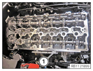
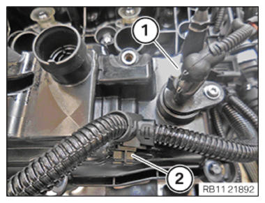
- Insert and install the cylinder head cover (1).
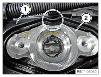
- Make sure the cylinder head cover (1) is correctly installed on the high pressure pump bracket (2) at the marked area.
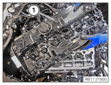
The cylinder head cover (1) must not tap the high pressure pump bracket (2) in the marked area.
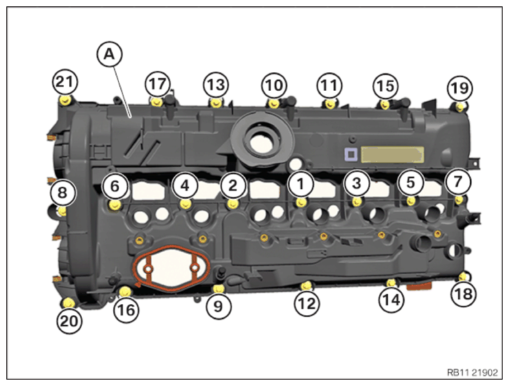
- Position the cylinder head cover (A).
- Make sure that the cylinder head cover (A) does not tap the high pressure pump bracket.
- Tighten all the screws in the order (1) to (21).
TIGHTENING TORQUES SPECIFICATION
| Cylinder head cover to cylinder head | |
| M6X30 | Joining torque 8 Nm |
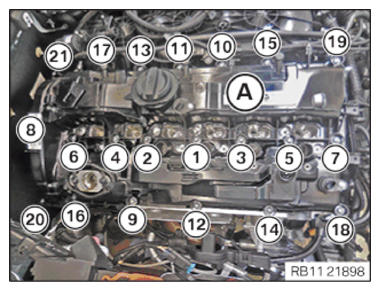
- Tighten all screws in a sequence from (1) to (21).
TIGHTENING TORQUES SPECIFICATION
| Cylinder head cover to cylinder head | |
| M6X30 | tightening torque 11 Nm |
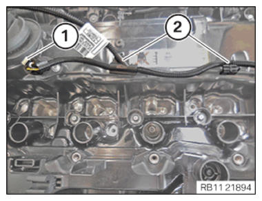
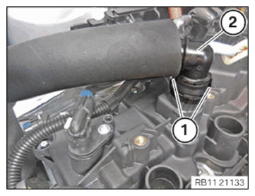
- Insert and install the engine ventilation line (2).
- Ensure that the locks (1) engage audibly.
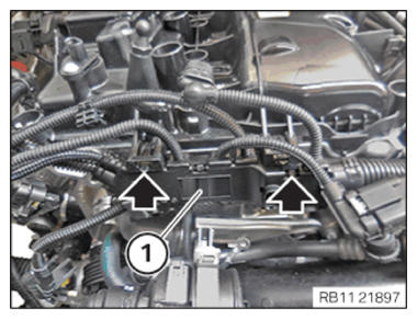
- Guide in and install wiring harness section (1) for sensor system 2.
- Make sure that you can hear the locks (arrows) engage.
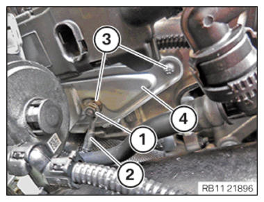
- Insert and position the holders (4).
- Tighten down screws (3).
TIGHTENING TORQUES SPECIFICATION
| Auxiliary coolant pump holder to cylinder head | |
| M6 | tightening torque 7 Nm |
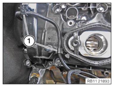
- Thread in ground cable (2) and install.
- Tighten nut (1).
TIGHTENING TORQUES SPECIFICATION
| Standard screw connection M6 | |
| M6 | Tightening torque 8 Nm |
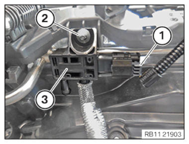
- Connect and lock the connector (1) to the exhaust camshaft sensor.
- Make sure the connector (1) engages audibly on the exhaust camshaft sensor.
- Secure clamps (2).
NOTE:
The following step(s) must be performed if the listed component(s) is/are installed.
- Feed in and install the differential pressure sensor (3).
- Tighten down screw (2).
TIGHTENING TORQUES SPECIFICATION
| Differential pressure sensor to holder | |
| TS6X18 | Tightening torque 3.5 Nm |
- Connect and lock the connector (1).
- Make sure the connector (1) engages audibly.
CAUTION:
Improper routing of the positive battery cable.
Risk of short circuits!
Risk of short circuits!
- Route the positive battery cable without abrasions and do not trap.
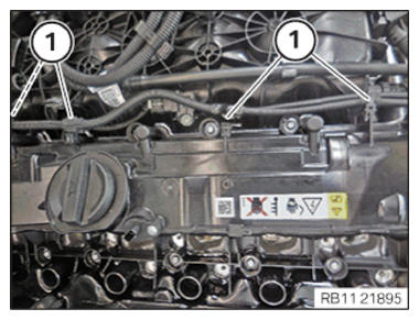
- Feed in the bracket (2) of positive battery cable and install.
- Tighten down screws (1).
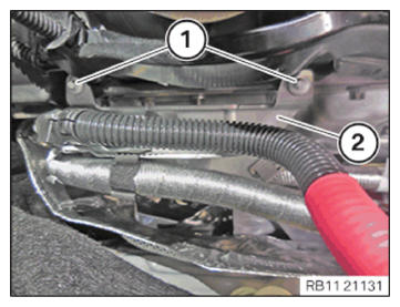
TIGHTENING TORQUES SPECIFICATION
| Holder, positive battery cable to cylinder head cover | |
| 6X18 | Tightening torque 6 Nm |
- Secure clamps (1).
- Secure clamps (1).
- Connect and lock the connector (1) on the intake camshaft sensor.
- Make sure the connector (1) engages audibly.
- Secure clamps (2).