Installing both charge air coolers
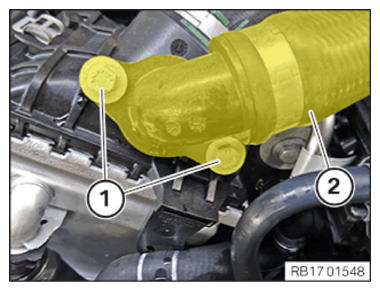
- Insert and position the right-hand charge air cooler (1).
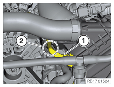
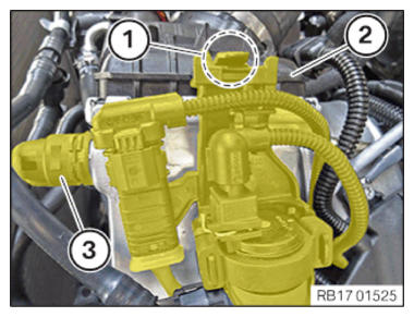
- Position the charge air cooler (1) as shown.
- Connect and lock the coolant line (2).
- Tighten down screw (3).
TIGHTENING TORQUES SPECIFICATION
| Charge air cooler to holder | |
| M6x35 | tightening torque 8 Nm |
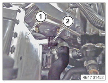
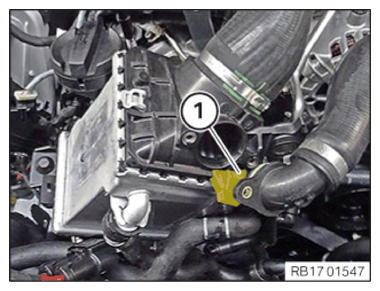
- Position the coolant line (1) from the charge air cooler (2) to the right and clip it in.
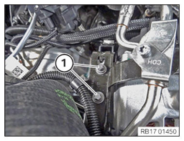
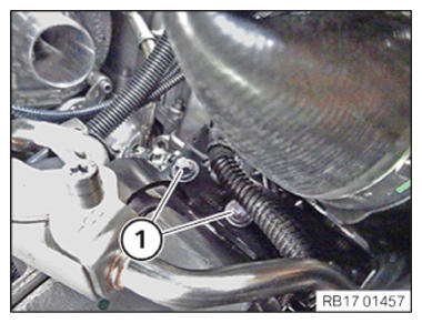
- Tighten down screws (1).
TIGHTENING TORQUES SPECIFICATION
| Alternator to cylinder head | |
| M8x85 | tightening torque 22 Nm |
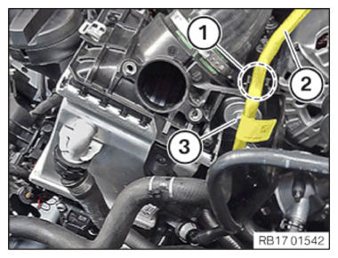
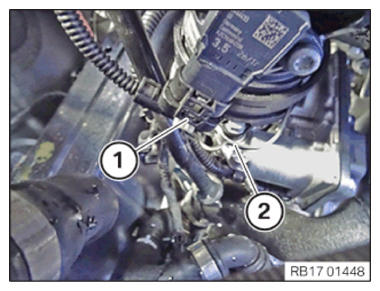
- Connect the bracket in the area (1) and lock it.
- Insert and install charge air line (2).
- Tighten down screws (1).
TIGHTENING TORQUES SPECIFICATION
| Connecting hose to charge air cooler | |
| Hexagon screw M6 | tightening torque 8 Nm |
- Lock clamp (2).
- Connect connectors (1) and lock.
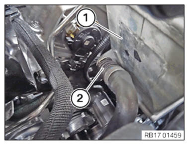
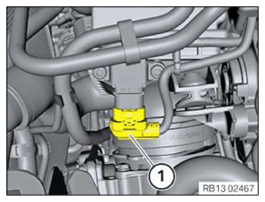
- Unlock the holder at the lock (1).
- Feed out the tank vent valve with holder (2) and place it on one side.
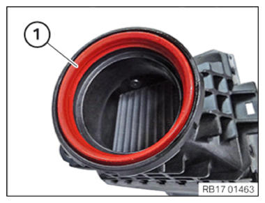
- Check the seal (1) for damage and replace if necessary.
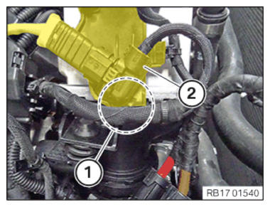
- Insert and position the left-hand charge air cooler.
- Position the charge air cooler (1) on the left as shown in the illustration.
- Connect and lock the coolant line (2).
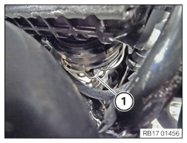
- Lock clamp (1).
The clamp (1) must engage audibly.
- Feed in coolant line (1) and clip it in within the area (2).
- Tighten down screw (1).
TIGHTENING TORQUES SPECIFICATION
| Charge air cooler to holder | |
| M6x35 | tightening torque 8 Nm |
- Tighten down screws (1).
TIGHTENING TORQUES SPECIFICATION
| Alternator to cylinder head | |
| M8x85 | tightening torque 22 Nm |
- Connect connectors (1) and lock.
- Connect and lock the coolant line (3).
The coolant line (3) must audibly engage.
- Feed in and install the tank vent valve with the bracket (2).
- Ensure that the locking mechanism (1) engages audibly.
Check the coolant level in the low-temperature coolant circuit and top up, if needed
CAUTION:
Materials harmful to health.
Contact with fluids harmful to health!
Contact with fluids harmful to health!
- Note and follow safety instructions on containers.
- Conduct all work in appropriate personal protective equipment only.
NOTE:
TECHNICAL INFORMATION
Follow notes for repair work on the cooling system.
For additional information see: NOTES FOR REPAIR WORK ON THE COOLING SYSTEM .
Follow notes for repair work on the cooling system.
For additional information see: NOTES FOR REPAIR WORK ON THE COOLING SYSTEM .
NOTE:
TECHNICAL INFORMATION
Immobilization period-long fill of coolant!
Do not reuse used coolant.
When replacing and removing components which rely on the corrosion protection effect of the coolant, it is essential to change the coolant. The cooling system must therefore be emptied and refilled.
In the case of other removal work involving the draining of part quantities of coolant, the coolant level must be topped up with new coolant.
NOTE:
TECHNICAL INFORMATION
Collect and dispose of emerging fluids. Observe country-specific waste disposal regulations.
Collect and dispose of emerging fluids. Observe country-specific waste disposal regulations.
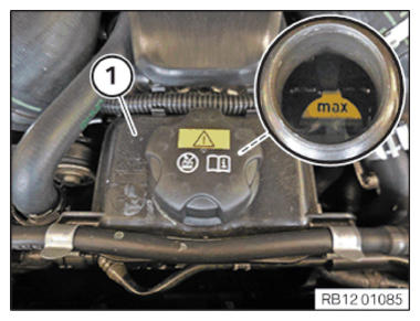
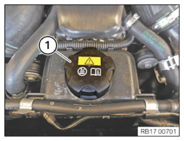
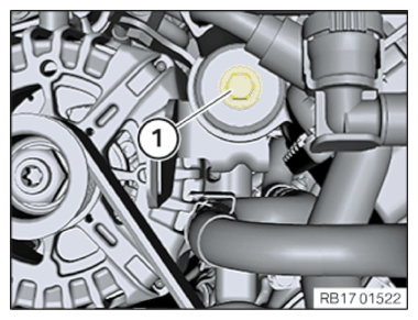
- Top up the coolant in the coolant expansion tank (1) for the low-temperature coolant circuit up to the maximum mark.
- Shut sealing cap (1).