Installing the right cylinder head
CAUTION:
Heavy component.
Heavy components can lead to injury or damage.
Heavy components can lead to injury or damage.
- Remove and install heavy components with the aid of another person/other persons.
CAUTION:
Swirling dirt particles caused by compressed air.
Injury hazard!
Injury hazard!
- Collect dirt particles, e.g. when blowing out, use cloth to do so.
- Wear safety goggles.
NOTE:
RISK OF DAMAGE
Damage to guide rails.
The application of great force can damage the guide rails of the timing chain.
Damage to guide rails.
The application of great force can damage the guide rails of the timing chain.
- When removing and installing the cylinder head, make sure that the cylinder head does not damage the guide rail.
NOTE:
RISK OF DAMAGE
Damage to the surface.
The use of metal-cutting tools (e.g., emery cloths) for cleaning surfaces can damage them and lead to leaks and/or engine damage.
Damage to the surface.
The use of metal-cutting tools (e.g., emery cloths) for cleaning surfaces can damage them and lead to leaks and/or engine damage.
- Do not use any metal-cutting tools.
NOTE:
TECHNICAL INFORMATION
When assembling, it is essential to observe screwing sequences and tightening torques.
Failure to comply with the regulations can lead to leaks and damage.
When assembling, it is essential to observe screwing sequences and tightening torques.
Failure to comply with the regulations can lead to leaks and damage.
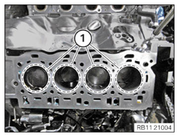
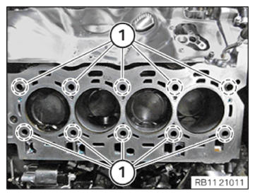
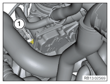
- Check if there are fluids or foreign materials present in the cylinder bores (1); remove fluids or foreign materials where required.
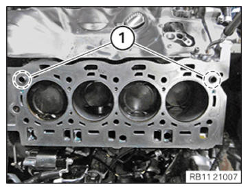
- Check the fitting sleeves (1) for correct seating and damage and replace if necessary.
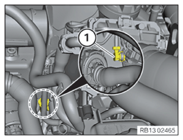
- Close the oil hole in the area (1) with a classification B plug from the set of special tools 2 364 711.
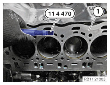
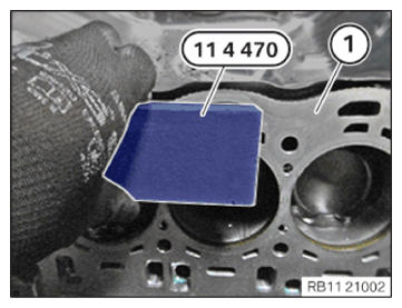
- Clean sealing surface (1)
with special tool 0495 103 (11 4 471)
from the set of special tools 0 495 102 (11 4 470).
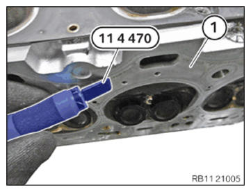
- Clean sealing surface (1)
with special tool 0495 104 (11 4 472)
from the set of special tools 0 495 102 (11 4 470).
- Clean bores of cylinder head bolts (1) with compressed air.
If foreign bodies or fluids are present in the bores, there is a danger that the tightening torque values are falsified.
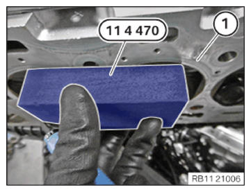
- Clean sealing surface (1) with special tool 0495 103 (11 4 471)
from the set of special tools 0 495 102 (11 4 470).
- Clean sealing surface (1) with special tool 0495 104 (11 4 472)
from the set of special tools 0 495 102 (11 4 470).
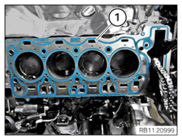
- Replace cylinder head gasket (1).
Parts: Cylinder head gasket
- Replace screws.
Parts: Screws
- Position cylinder head gasket (1) on the fitting sleeves on the engine block.
If the cylinder head was reworked, a thicker cylinder head gasket must be installed.
NOTE: TECHNICAL INFORMATION
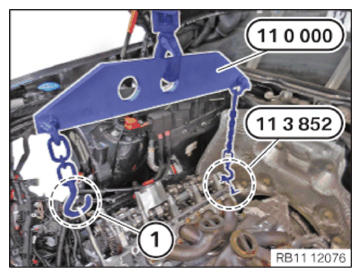
The work must be performed with vehicle care to prevent component damage. - Attach the special tool 0 490 561 (11 0 000) on the retaining tab (1) and on the special tool 0 494 116 (11 8 352) from the set of special tools 0 493 997 (11 8 350).
- Position cylinder head with a workshop crane.NOTE: TECHNICAL INFORMATION
The work must be performed with vehicle care to prevent component damage. - Carefully feed In and Install the cylinder head with a workshop crane and three support persons.
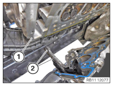
- When feeding In and Installing the cylinder head (1), make sure that the slide rails and timing chain (2) are not damaged.
- Detach the special tool 0 490 567 (11 0 020)
on the retaining tab (1) and on the special tool 0 494 116 (11 8 352)
from the set of special tools 0 493 997 (11 8 350).
Tightening right cylinder head
Tightening the right cylinder head
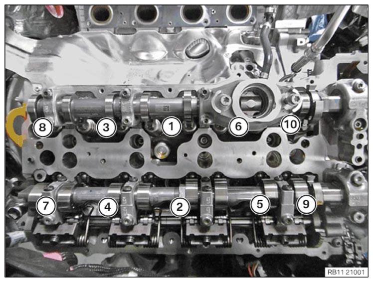
- Tighten screws in the order (1) to (10).TIGHTENING TORQUES SPECIFICATION
Cylinder head bolt M11 Replace screws. Joining torque 30 Nm 1. Angle of rotation 90° 2. Angle of rotation 140° - Detach the special tool 0 490 567 (110 020) on the engine mounting bracket and on the special tool 0 494 116 (11 8 352) from the set of special tools 0 493 997 (11 8 350).
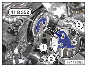
- Loosen screw (1).
- Remove the special tool 0 494 116 (11 8 352)
from the set of special tools 0 493 997 (11 8 350)
(2) from the support (3).
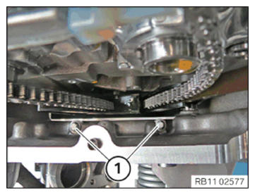
- Secure the screws (1) to the timing case cover.TIGHTENING TORQUES SPECIFICATION
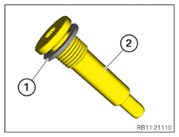
Cylinder head bolt to timing case cover M8x30 tightening torque 23 Nm - Replace sealing ring (1).
Parts: Sealing ring
- Position sealing ring (1) on the bearing screw (2).
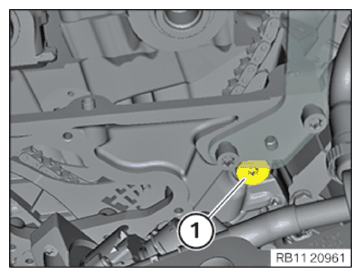
- Position the slide rail.
- Tighten the screw (1) of the slide rail on the cylinder head of cylinder bank.TIGHTENING TORQUES SPECIFICATION
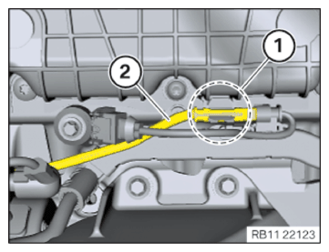
Slide rail to cylinder head Bearing screw Tightening torque 25 Nm - Clip the line (2) into the holder in area (1).
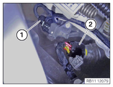
- Connect the quick-release coupling (1) and lock.
- Connect and lock the plug connection (1) of the throttle valve.
- Connect the connector (1) to the pressure sensor on the intake plenum and lock audibly.
- Connect the connector (2) to the servomotor and lock audibly.
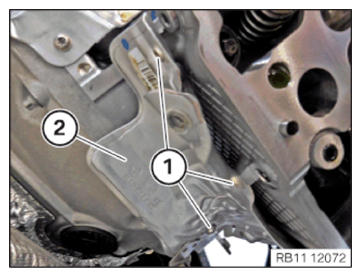
- Install the heat shield (2) on the rear of the cylinder head.
- Tighten down screws (1).TIGHTENING TORQUES SPECIFICATION
Heat protection plate M6x16 tightening torque 10 Nm