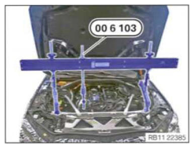
Move the engine to the installation position
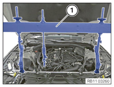
Prepared engine bridge
CAUTION:
Components connected to the engine joint or cross member.
Injury hazard!
Injury hazard!
- Check lifting eyes and engine mounting brackets for damage, e.g. cracks.
- Attach the component to correctly mounted engine joints or cross members only.
- Only lift the component, do not shift it forwards, backwards or in transverse direction.
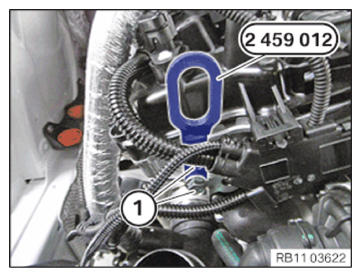
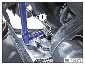
- Insert and position the special tool 2 459 012 at the cylinder head.
- Tighten the screws (1) of the special tool 2 459 012. TIGHTENING TORQUES SPECIFICATION
Special tool to cylinder head M8 Tightening torque 21.5 Nm - Release the screws (1) left and right.
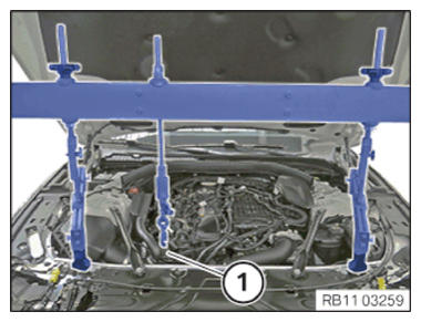
- Position engine bridge (1) carefully
with a support person.
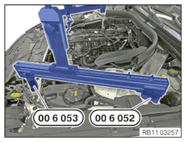
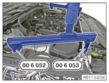
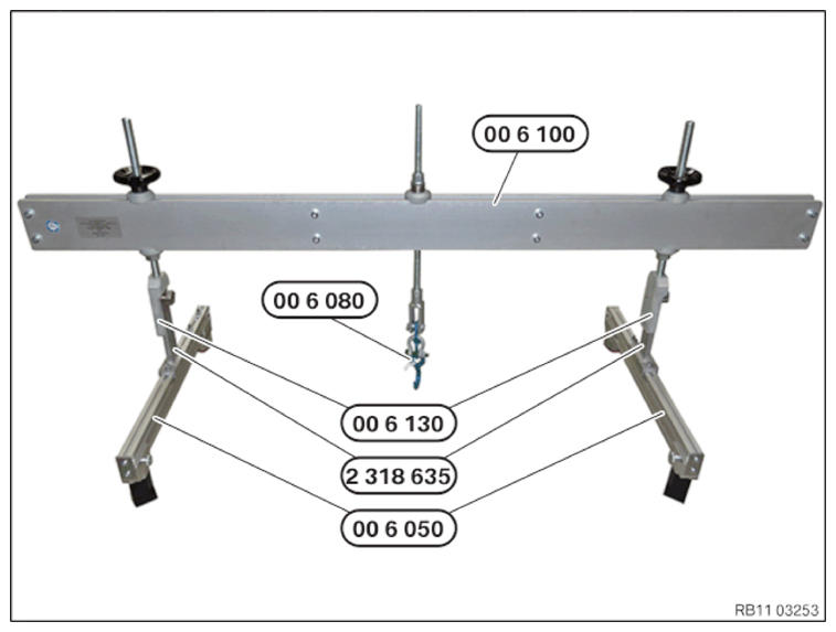
- Make sure that the special tool 0 496 438 (00 6 053) from the set of special tools 0 496 430 (00 6 050) , left, rests correctly on the lock support.
- Make sure that special tool 0 496 437 (00 6 052)
from the set of special tools 0 496 430 (00 6 050),
left, rests correctly on the shock tower.
- Make sure that the special tool 0 496 438 (00 6 053) from the set of special tools 0 496 430 (00 6 050) , right, rests correctly on the lock support.
- Make sure that special tool 0 496 437 (00 6 052)
from the set of special tools 0 496 430 (00 6 050),
right, rests correctly on the shock tower.
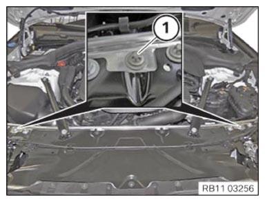
- By shifting the engine bridge on the profile strips of the special tool 0 496 430 (00 6 050), align it above the engine mounting bracket (1) and screw in place.
- Align hook 0 496 733 (00 6 080) above engine mounting bracket (1).
- Connect hook 0 496 733 (00 6 080)
to engine mounting bracket (1).
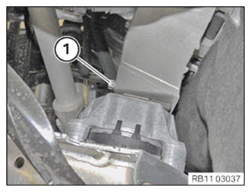
- Release screw (1) on left engine support bracket from the bottom.
- Release the screw (1) on the engine support bracket on the right from the top.
- Lift the engine by turning the special tool by 10 mm.