Blocking engine in TDC firing position
- Guide out and remove sealing cap (1).NOTE: RISK OF DAMAGE
Damage to the engine.
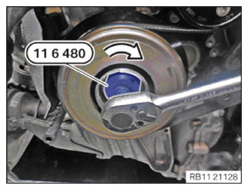
If the engine is manually rotated in the wrong direction of rotation, the engine can be damaged.- Only rotate the engine manually in the correct direction of rotation: a) clockwise when looking at the damper, or b) counterclockwise when looking at the chain drive, b) applies only if the timing chain is installed in the rear.
- With the special tool 0 493 380 (11 6 480), turn the engine in arrow direction to the TDC firing position of cylinder 1.
- Vehicles with automatic transmission:
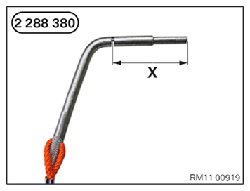
Dimension (X) = 66 mm
Special tool 2 288 380 must be inserted up to dimension (X) into the dowel hole.
- Vehicles with automatic transmission:
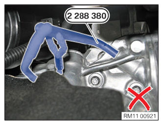
The special tool 2 288 380 is incorrectly positioned.
TDC firing position of cylinder 1 not achieved.
- Vehicles with automatic transmission:
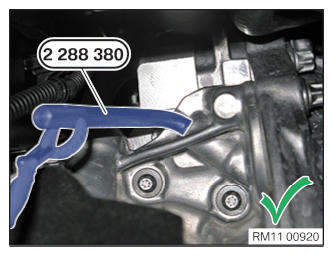
The special tool 2 288 380 is correctly positioned.
Engine in TDC firing position of cylinder 1.
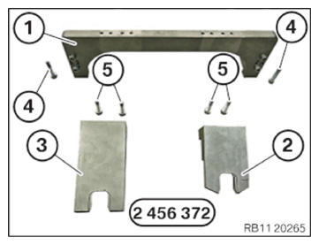
- Keep the set of special tools 2 456 372
at hand:
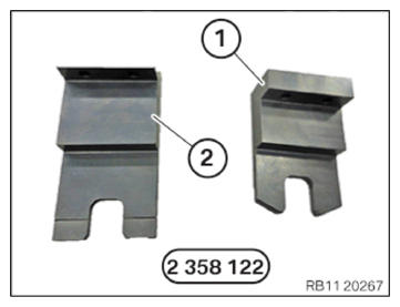
Number Description 1 Basic carrier 2 Setting gauge for adjusting the intake camshaft 3 Setting gauge for adjusting the exhaust camshaft 4 Basic carrier screws on cylinder head 5 Screw gauge on basic carrier - Have the test gauges from the set of special tools 2 358 122
ready:
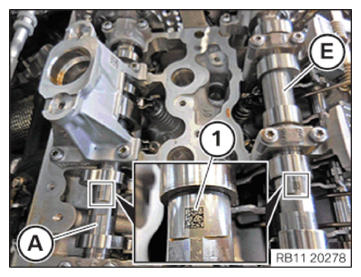
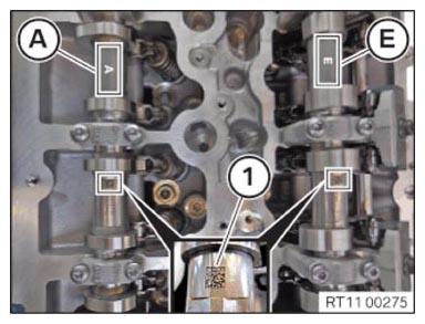
Number Description 1 Test gauges for fixing in place the intake camshaft 2 Test gauges for fixing in place the exhaust camshaft - Rotate the intake camshaft (E) and the exhaust camshaft (A) so that the marks (1) are legible from above.
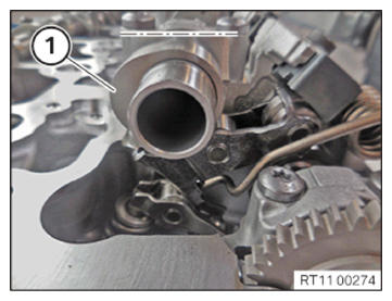
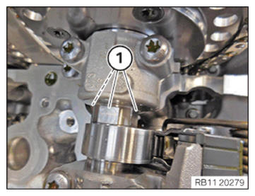
- Make sure the cam (1) on the exhaust camshaft on cylinder 1
is pointing slightly to the inside right at an angle.
- Make sure the cam (1) on the intake camshaft on cylinder 1
is pointing leftwards at an angle.
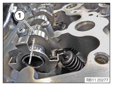
- Make sure the flattened areas (1) on the intake camshaft and the exhaust camshaft are pointing upwards at an angle.
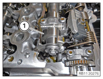
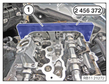
- Position the basic carrier (1) from the set of special tools 2 456 372
on the cylinder head.
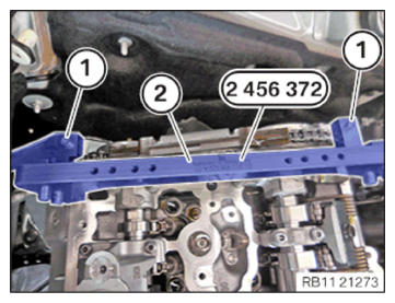
- Tighten the screws (1) from special tool set 2 456 372
on the basic carrier (2).TIGHTENING TORQUES SPECIFICATION
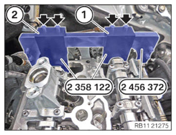
Basic carrier to cylinder head M6 Tightening torque 8 Nm - Position the test gauge (1) from the set of special tools 2 358 122 between the intake camshaft and the basic carrier from the set of special tools 2 456 372.
- Position the test gauge (2) from the set of special tools 2 358 122 between the exhaust camshaft and the basic carrier from the set of special tools 2 456 372.
- Tighten the screws (arrows).TIGHTENING TORQUES SPECIFICATION
Test gauge to basic carrier M6 Tightening torque 8 Nm
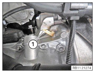
- Guide out and remove sealing cap (1).NOTE: RISK OF DAMAGE
Damage to the engine.
If the engine is manually rotated in the wrong direction of rotation, the engine can be damaged.- Only rotate the engine manually in the correct direction of rotation: a) clockwise when looking at the damper, or b) counterclockwise when looking at the chain drive, b) applies only if the timing chain is installed in the rear.
- With the special tool 0 493 380 (11 6 480), turn the engine in arrow direction to the TDC firing position of cylinder 1.
- Vehicles with automatic transmission:
Dimension (X) = 66 mm
Special tool 2 288 380 must be inserted up to dimension (X) into the dowel hole.
- Vehicles with automatic transmission:
The special tool 2 288 380 is incorrectly positioned.
TDC firing position of cylinder 1 not achieved.
- Vehicles with automatic transmission:
The special tool 2 288 380 is correctly positioned.
Engine in TDC firing position of cylinder 1.
- Vehicles with manual gearbox:
Dimension (X) = 62 mm
Special tool 2 288 380 must be inserted up to dimension (X) into the dowel hole.
- Vehicles with manual gearbox:
The special tool 2 288 380 is incorrectly positioned.
TDC firing position of cylinder 1 not achieved.
- Vehicles with manual gearbox:
The special tool 2 288 380 is correctly positioned.
Engine is in TDC firing position of cylinder 1.
- Have the set of special tools 2 456 372
ready:
Number Description 1 Basic carrier 2 Setting gauge for adjusting the intake camshaft 3 Setting gauge for adjusting the exhaust camshaft 4 Basic carrier screws on cylinder head 5 Screw gauge on basic carrier - Have the test gauges from the set of special tools 2 358 122
ready:
Number Description 1 Test gauges for fixing in place the intake camshaft 2 Test gauges for fixing in place the exhaust camshaft - Make sure the marks (1) on the intake camshaft (E) and the exhaust camshaft (A) are legible from above.
- Make sure the cam (1) on the exhaust camshaft on cylinder 1
is pointing slightly to the inside right at an angle.
- Make sure the cam (1) on the intake camshaft on cylinder 1
is pointing leftwards at an angle.
- Make sure the flattened areas (1) on the intake camshaft and the exhaust camshaft are pointing upwards at an angle.
- Position the basic carrier (1) from the set of special tools 2 456 372
on the cylinder head.
- Tighten the screws (1) from special tool set 2 456 372
on the basic carrier (2).TIGHTENING TORQUES SPECIFICATION
Basic carrier to cylinder head M6 Tightening torque 8 Nm - Position the test gauge (1) from the set of special tools 2 358 122 between the intake camshaft and the basic carrier from the set of special tools 2 456 372.
- Position the test gauge (2) from the set of special tools 2 358 122 between the exhaust camshaft and the basic carrier from the set of special tools 2 456 372.
- Tighten the screws (arrows).TIGHTENING TORQUES SPECIFICATION
Test gauge to basic carrier M6 Tightening torque 8 Nm