Installing the cylinder head of cylinder bank 1 on the assembly jig
CAUTION:
Heavy component.
Heavy components can lead to injury or damage.
Heavy components can lead to injury or damage.
- Remove and install heavy components with the aid of another person/other persons.
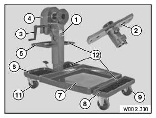
- Get the set of special tools 0 495 187 (00 2 300)
ready.
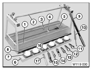
Number Description 1 Assembly jig 2 Flange 3 Crank 4 cover panel 5 shelf 6 Rear shaped part 7 Collecting vessel 8 Front shaped part 9 Front wheel 10 Rear wheel with stop 11 Rubber mat - Get the set of special tools 0 494 362 (11 9 000)
ready.
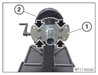
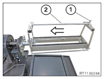
Number Description 1 Device 2 Rod 3 Adapter 4 Lug 5 Quick tensioning device 6 Aluminum frame insert 7 Shaped part 8 Plastic shaped part 9 lever 10 hook 11 Valve spring cage 12 Valve spring cage 13 Valve spring cage 14 Valve spring cage 15 Valve spring cage 16 Valve spring cage 17 Valve spring cage - Position flange (1) on the assembly jig (2).
- Tighten screws (arrows).TIGHTENING TORQUES SPECIFICATION
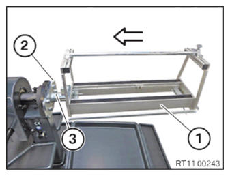
Flange to assembly jig M14X30 Tightening torque 135 Nm - Slide the device (1) in arrow direction onto the flange (2) and install.
- Make sure that the lock (3) engages audibly.
- Loosen screw (1).
- Feed out rod (2) in arrow direction and set aside.
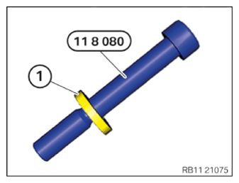
- Keep the screws from the set of special tools 0 496 408 (11 8 080) ready.
- The washer of the cylinder head bolt (1) must be used.
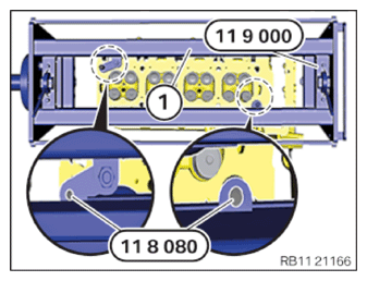
- Apply the cylinder head (1) hand-tight on the special tool 0 494 362 (11 9 000)
in the attachment point area using the screws from the set of special tools 0 496 408 (11 8 080)
.