Installing the engine on the assembly jig
CAUTION:
Heavy component.
Heavy components can lead to injury or damage.
Heavy components can lead to injury or damage.
- Remove and install heavy components with the aid of another person/other persons.
- Get the set of special tools 0 495 187 (00 2 300)
ready.
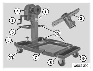
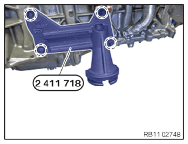
Number Description 1 Assembly jig 2 Flange 3 Crank 4 cover panel 5 shelf 6 Rear shaped part 7 Collection pan 8 Front shaped part 9 Front wheel 10 Rear wheel with stop 11 Mat - Have the special tool 2 411 718
ready.
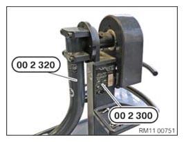
- Position the assembly jig 0 495 187 (00 2 300)
with the special tool 0 495 196 (00 2 320).
- Tighten the screws (arrows).TIGHTENING TORQUES SPECIFICATION
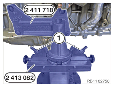
Special tool 00 2 320 to special tool 00 2 300 M14X95 Tightening torque 130 Nm - Screw the special tool 2 413 082 to the 0 495 196 (00 2 320) special tool.
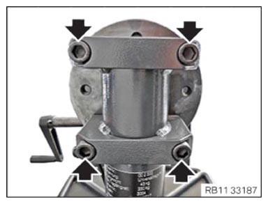
- Tighten the screws (arrows).TIGHTENING TORQUES SPECIFICATION
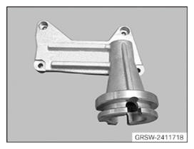
Special tool 2 413 082 to special tool 00 2 320 M 12x65 Tightening torque 100 Nm - Position and secure the special tool (motor mount) 2 411 718 on the engine.
- Tighten the screws (marks).TIGHTENING TORQUES SPECIFICATION
Special tool 2 411 718 to crankcase M10x30 tightening torque 38 Nm - Slowly lower the engine.
- Ensure that special tool 2 411 718 engages in special tool 2 413 082.
- Hand-tighten nuts (1).
The clamping jaws must make full contact.
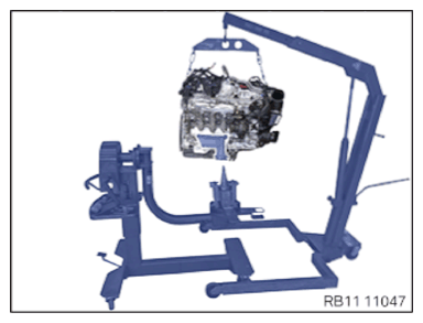
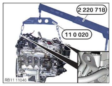
- Release both hooks of the special tool (lifting equipment) 0 490 567 (11 0 020) at the front and rear of the engine from the mounting brackets.
- Remove the workshop crane 2 220 718.