Installing the injectors for the cylinders 1 to 4
Preparing the injectors for installation
Damage to the injector tips and Teflon ring.
Improper handling of the injector tips and Teflon ring can lead to malfunctioning of the injector.
- Avoid mechanical contact with injector tip.
- When exchanging Teflon ring, hands and work surface must be clean and free of oil. Do not use any lubricating agents.
- Do not use fingernails to slide Teflon ring on.
Before re-exchanging the injector, the Teflon ring must be replaced. Once a Teflon ring has been installed, it may not be re-used. New injectors are supplied with a new Teflon ring.
After installation of a new Teflon ring on the injectors, the injector must be installed in the cylinder head within 10 minutes or protected with protective caps; otherwise, the Teflon ring will swell.
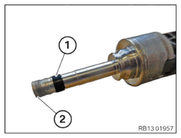
- Before installing the injectors: Replace the Teflon rings (1).
Parts: Teflon rings
- Avoid mechanical contact with injector tip (2).
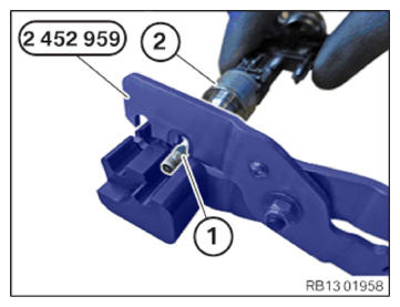
- Remove Teflon ring (1) by using special tool 2 452 959 from injector (2).
- If necessary, use a lint-free cloth to clean the cylindrical part of the injector tip. Do not use ultrasonic sound or other auxiliary materials.
- Do not
clean injector tip.
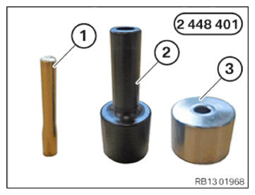
- For installing the new Teflon ring: Use 2 448 401
set of special tools:
- Installation cone
- Sliding sleeve
- Assembly sleeve
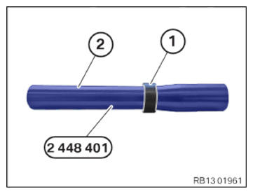
- Slide the new Teflon ring (1) onto the installation cone (2) from the set of special tools 2 448 401.
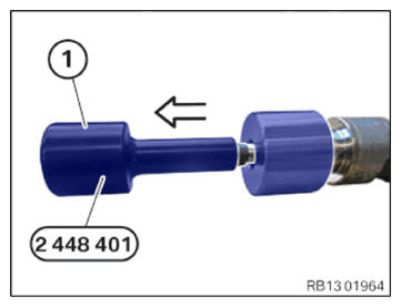
- Ensure correct installation position of the assembly sleeve (1) from the set of special tools 2 448 401:
The larger diameter of the assembly sleeve (1) must point to the injector tip.
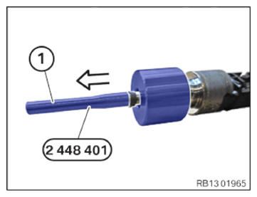
- Ensure correct installation position of the assembly sleeve (1) from the set of special tools 2 448 401:
The assembly sleeve (1) is not mounted correctly if the smaller diameter points to the injector tip.
- Mount the Teflon ring (2) with the installation cone (1) from the set of special tools 2 448 401
on the injector tip.
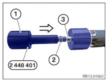
- Slide the Teflon ring (2) by using the sliding sleeve (1) from the set of special tools 2 448 401
in arrow direction into the groove (3) on the injector.
- Feed out and remove the sliding sleeve (1) from the set of special tools 2 448 401
in arrow direction.
- Feed out and remove the installation cone (1) from the set of special tools 2 448 401
in arrow direction.
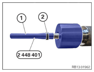
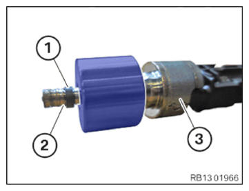
- Make sure that the widened Teflon ring (1) is placed clean in the groove (2) of the injector (3) and can be easily moved with fingers.
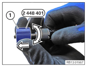
- Calibrate the widened Teflon ring with the assembly sleeve (1) from the set of special tools 2 448 401 in arrow direction to the installation dimension.
- Make rotational movements
in increments of 180° synchronous to the detaching movement.
While doing so, move slowly and not
jerkily.
This calibrates the Teflon ring (1) to the installation dimension.
- Guide out and remove assembly sleeve (1).
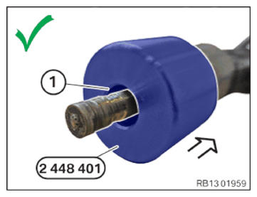
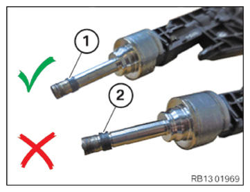
- Check if the installation dimension of the Teflon ring (1) is correct:
- (1) Shows that the Teflon ring has the correct installation dimension.
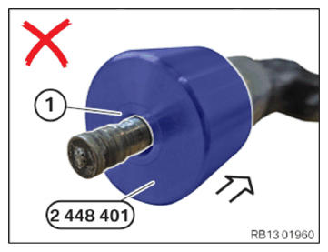
- (2) Shows that the Teflon ring does not have the correct installation dimension.
Install injectors
NOTE: TECHNICAL INFORMATION
When assembling, it is essential to observe screwing sequences and tightening torques.Failure to comply with the regulations can lead to leaks and damage.
NOTE: The description is for one component only. The procedure is identical for all further components.Retrofitting and, if necessary, replacing the foam jacket
NOTE: The description is for one component only. The procedure is identical for all further components.Check
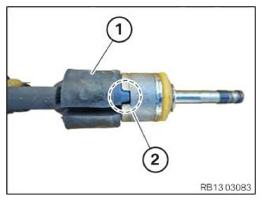
- Check if foam jacket (1) is installed on injector (2).
Result
» Foam jacket (2) is not installed.
Measure
- Retrofit foam jacket (2) as described in the following step.
Parts: Foam jacket
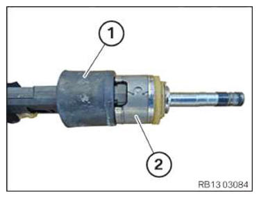
Result
» Foam jacket (2) is installed.
Measure
- Replace foam jacket (2) as described in the following step.
Parts: Foam jacket
- Position foam jacket (1) in the recess of the injector in area (2).
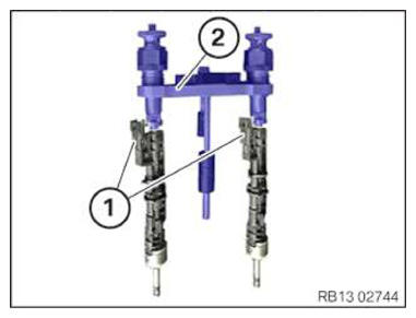
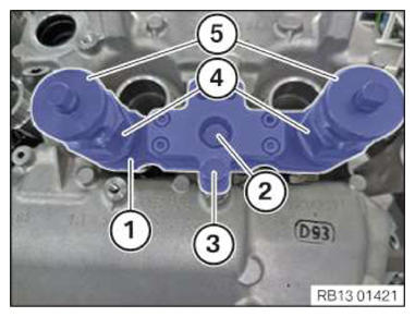
- Mount the injectors (1) on the special tool (2) 2 410 777.
- Align the plug connections of injectors (1) in the correct installation position.
- Insert the injectors in the injector bore holes with special tool (1) 2 410 777.
- Screw in the screws (2) and (3) on the injector shaft with a few thread starts.
- Check, if the pull-out thread (4) and the threaded sleeves (5) are correctly mounted.
- Tighten screws (2) and (3).TIGHTENING TORQUES SPECIFICATION
Special tool 2 410 777 to injector well M6 tightening torque 8 Nm - Adjust the torque wrench (1) to 2 Nm, counter-clockwise.
- Position the torque wrench (1) and special tool (2) 0 496 106 (11 8 720) on the hexagon head of special tool 2 410 777.
- Turn the torque wrench (1) in anti-clockwise direction until 2 Nm apply.
- Remove special tool 2 410 777.
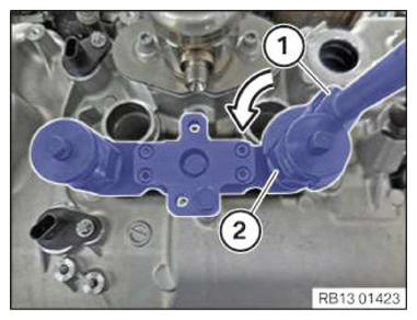
- Install hold-down device (1) with curvatures (see arrow) downwards.
- Mount the hold-down device (2) on the injectors.
- Screw in the screw (1) by a few turns only.