Remove the injectors for cylinders 1 to 4
Remove injectors
NOTE:
RISK OF DAMAGE
Contaminant or foreign body.
Contamination can result in malfunctions, loss of function or leaks.
Contaminant or foreign body.
Contamination can result in malfunctions, loss of function or leaks.
- Adhere to the utmost cleanliness.
- Protect components from contamination e.g. by covering.
- Close off line connections with seal plugs.
NOTE:
RISK OF DAMAGE
Damage to the ignition coil.
The silicone hose of the ignition coil must not be contaminated by fuel as this can lead to failure of the ignition coil.
Damage to the ignition coil.
The silicone hose of the ignition coil must not be contaminated by fuel as this can lead to failure of the ignition coil.
- When working on the fuel system, cover the ignition coils with suitable materials and remove where required.
- Do not oil or grease the silicone tube of the spark plug socket. Do not use any protection or maintenance products (e.g. silicone spray, rubber care products, rust remover, etc.).
NOTE:
RISK OF DAMAGE
Damage to the injector tips and Teflon ring.
Improper handling of the injector tips and Teflon ring can lead to malfunctioning of the injector.
Damage to the injector tips and Teflon ring.
Improper handling of the injector tips and Teflon ring can lead to malfunctioning of the injector.
- Avoid mechanical contact with injector tip.
- When exchanging Teflon ring, hands and work surface must be clean and free of oil. Do not use any lubricating agents.
- Do not use fingernails to slide Teflon ring on.
NOTE:
RISK OF DAMAGE
Damage to injectors.
Excessive force may damage the injector and this means having to replace the injector.
Damage to injectors.
Excessive force may damage the injector and this means having to replace the injector.
- Twist the injectors with a torsional movement of maximum 13 Nm.
NOTE:
The description is for one component only. The procedure is identical for all further components.
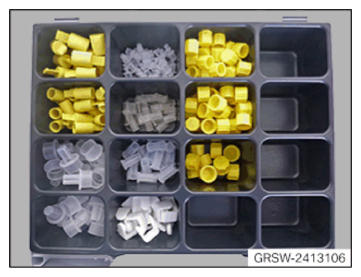
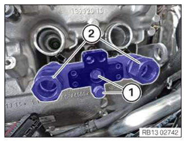
- Prepare special tool 2 413 106.
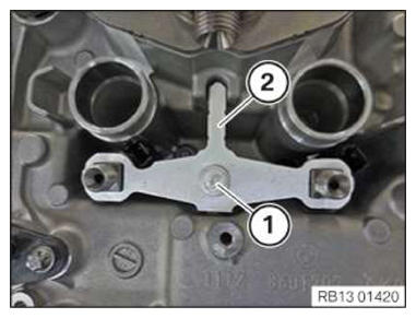
- Loosen screw (1).
- Remove hold-down device (2).
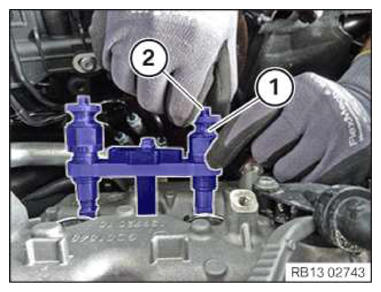
- Pull injectors upward out of cylinder head and remove.
If several injectors are removed, ensure that each injector is reinstalled in its original installation location (cylinder):
- Mark injectors.
To not exceed the maximum tensile force of 2000 N when pulling out the fixed injectors: Use special tool 2 410 777! Using a correctly adjusted torque wrench and special tool 2 410 777 ensures that the maximum tensile force of 2000 N will not be exceeded at the injectors.
The injector must be replaced if the torque wrench clicks when the injector is pulled out.
- Unscrew the pull-out thread (1) from the special tool 0496 885 (13 0320).
- Screw in the pull-out thread (1) from special tool 0 496 885 (13 0 320) into special tool 2 410 777.
- Lightly oil the pull-out thread (1) before using the special tool 2 410 777
and fully unscrew as shown.
The pull-out threads (1) are left-hand threads.
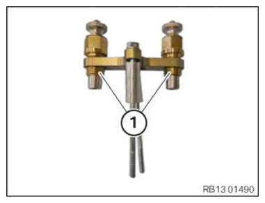
- Position the special tool 2 410 777 on the injector shaft.
- Screw in the screws (1) on the injector shaft for a few thread starts.
- Fully screw in the pull-out thread (2).
- Screw on the threaded sleeves (1) on to the injectors until the retaining pin (2) grips.
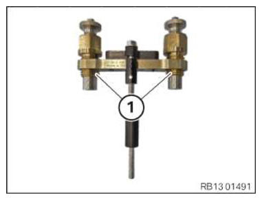
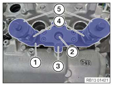
- Tighten the screws (2) and (3) of the special tool 2 410 777
(1).TIGHTENING TORQUES SPECIFICATION
Special tool 2 410 777 to injector well M6 tightening torque 8 Nm - Check whether the pull-out threads (4) are screwed in fully.
- Check whether the threaded sleeves (5) at the injectors are screwed on and retained.
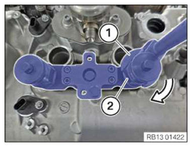
- Adjust the torque wrench (1) to 13 Nm in a clockwise rotation.
- Apply the torque wrench (1) and the special tool (2) 0 496 106 (11 8 720) to the hexagon head of the special tool 2 410 777.
- Turn the torque wrench (1) in the direction of arrow until the injector has been pulled out.
The injector must be replaced if the torque wrench clicks when the injector is pulled out.
- Disassemble the special tool 2 410 777
and remove the injector.