Removing the cylinder head cover
NOTE:
DANGER
High-voltage system.
The high-voltage system operates on the basis of hazardous, electrical voltage and high currents. Danger to life through electric shock!
High-voltage system.
The high-voltage system operates on the basis of hazardous, electrical voltage and high currents. Danger to life through electric shock!
- All work on the high-voltage system may only be carried out by specially trained and technically experienced personnel.
- For additional information see:
- For additional information see:
WARNING:
Hot surfaces.
Risk of burning!
Risk of burning!
- Perform all work only on components that have cooled down.
WARNING:
Working on fuel system.
Risk of fire! Danger of explosion!
Risk of fire! Danger of explosion!
- When working on the fuel system, make sure that the workbay is sufficiently ventilated, e.g. using extraction unit.
- Tightly seal off open lines and connections; collect any escaping fuel directly at the point of exit.
- No fire, sparks, open flames or smoking.
CAUTION:
On releasing high pressure line, fuel may emerge at high speed.
Danger of injury!
Danger of injury!
- Wear suitable personal protective equipment.
- Allow the cooling system to cool down to a temperature below 40°C before starting installation work.
- Note warnings on cylinder head cover.
NOTE:
TECHNICAL INFORMATION
Collect and dispose of emerging fluids. Observe country-specific waste disposal regulations.
Collect and dispose of emerging fluids. Observe country-specific waste disposal regulations.
Preliminary work:
- Refer to REMOVING THE ACOUSTIC COVER .
- Refer to REMOVING INTAKE SILENCER HOUSING .
- Refer to REMOVING THE CYLINDER HEAD COVER ACOUSTIC COVER .
- Refer to REMOVING RESONATOR .
- Refer to REMOVING CLEAN AIR PIPE .
- Refer to REMOVING CHARGE AIR LINE .
- Refer to REMOVING FRONT UNDERBODY PROTECTION AND/OR FRONT STIFFENING PLATE .
- Refer to REMOVING THE UNDERBODY PROTECTION OF THE STEERING GEAR AND FRONT STIFFENING PLATE RESPECTIVELY .
- Refer to DRAINING THE COOLANT FROM THE HIGH-TEMPERATURE COOLING SYSTEM .
- Refer to REMOVING THE ACOUSTIC COVER FOR THE ENGINE AT THE FRONT .
- Refer to REMOVING AUXILIARY COOLANT PUMP FOR THE EXHAUST TURBOCHARGER .
- Refer to REMOVING FRONT ENGINE ENCAPSULATION .
- Refer to REMOVING THE SEAL FOR THE REAR BONNET .
- Refer to REMOVING ACOUSTIC COVER AT REAR .
- Refer to REMOVING THE COVER OF THE ENGINE COMPARTMENT AT THE REAR LEFT .
- Refer to REMOVING LEFT AND RIGHT WIPER ARM .
- Refer to REMOVING COWL PANEL COVER .
- Refer to REMOVING TRAILING LINK AT SPRING BOLT .
- Refer to REMOVING THE CENTER BULKHEAD UPPER PART .
- Refer to REMOVING RIGHT SEALING FRAME .
- Refer to FASTENING HIGH-VOLTAGE CABLES ON THE ELECTRICAL MACHINE ELECTRONICS .
- Refer to REMOVING LEFT SEALING FRAME .
- Refer to REMOVING THE CENTER BULKHEAD LOWER SECTION .
- Refer to REMOVING BOTH ACTUATORS .
- Refer to REMOVING IGNITION COILS .
- Refer to REMOVING THE HIGH PRESSURE LINE BETWEEN THE HIGH PRESSURE PUMP AND THE RAIL .
- Refer to REMOVING FUEL DELIVERY LINE .
- Refer to REMOVING HIGH PRESSURE PUMP .
- Refer to REMOVING INJECTORS .
NOTE:
TECHNICAL INFORMATION
Collect and dispose of emerging fluids. Observe country-specific waste disposal regulations.
Collect and dispose of emerging fluids. Observe country-specific waste disposal regulations.
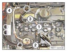
- Have a rag ready and make sure that no motor oil drips onto the belt drive.
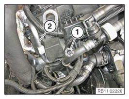
- Loosen screw (1).
- Detach the oil feed line (2).
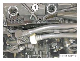
- Unlock and detach the engine wiring harness (1) in the highlighted areas.
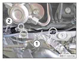
- Unhook the two oxygen sensor cables (1) in the marked areas.
- Detach the positive battery cable (2) in the highlighted area.
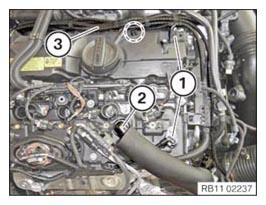
- Unlock both plug connections (1) and disconnect.
- Unlock and pull off the engine ventilation line (2).
- Detach the engine wiring harness (3) in the highlighted area.
- Loosen both oxygen sensor connectors (1) from the carrier plate.
- Release screw (2) and keep the carrier plate aside.
- Detach the cables in the marked areas.
- Detach the engine wiring harness (3) in the highlighted area.
- Release screw (4) and keep the fuel supply line aside.
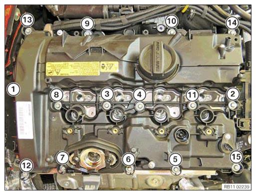
- Release the screws in the order from (15) to (1).
- Remove cylinder head cover.