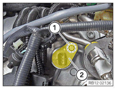
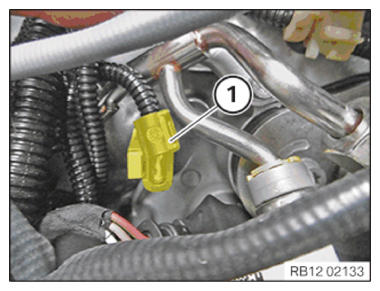
Installing the exhaust camshaft sensor of cylinder bank 2
- Position exhaust camshaft sensor of cylinder bank 1 (2).
- Tighten down screw (1).
TIGHTENING TORQUES SPECIFICATION
| Camshaft position sensor | ||
| M6x16 screw | Tightening torque | 8 Nm |
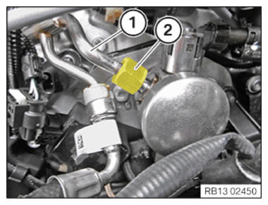
- Position fuel line (1).
- Tighten nut (2).
TIGHTENING TORQUES SPECIFICATION
| Fuel delivery line to high pressure pump | ||
| M14 | Tightening torque | 30 Nm |
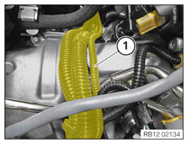
- Push aside the wiring harness in area (1).
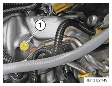
- Tighten down screw (1).
TIGHTENING TORQUES SPECIFICATION
| Fuel line | ||
| M6x16 | Tightening torque | 10 Nm |
- Push the wiring harness (1) to the side.
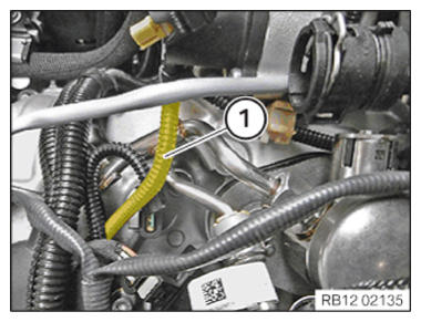
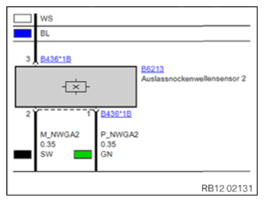
- The plug connection of the exhaust camshaft sensor and the ignition coil can be confused, as they are encoded the same. Observe the cable colors in the wiring diagram.
- Connect plug connection (1) and lock.
Follow-up work
- Refer to INSTALL IGNITION COIL ON CYLINDER 5 .
- Refer to INSTALLING THE CONTROL UNIT BRACKET FOR CYLINDERS 5 TO 8 .
- Refer to INSTALLING THE CLEAN AIR PIPE OF CYLINDER BANK 2 .
- Refer to CONNECTING THE LEFT CHARGE AIR LINE TO THE EXHAUST TURBOCHARGER .
- Refer to INSTALLING LEFT INTAKE FILTER HOUSING WITH LEFT FRONT-END STRUT .
- Refer to INSTALLING THE COVER OF THE LEFT DME CONTROL UNIT .
- Refer to INSTALLING ACOUSTIC COVER .