Replacing the NTC
WARNING:
Note the following before removing the high-voltage battery unit!
Before removing the high-voltage battery unit, it must be ensured that the state of charge of the vehicle is below a state of charge of 50%.
Before removing the high-voltage battery unit, it must be ensured that the state of charge of the vehicle is below a state of charge of 50%.
- If the state of charge is above 50%, the high-voltage battery unit must be discharged.
NOTE:
TECHNICAL INFORMATION
All parts for this procedure are included in the scope of parts 8 849 422.
In addition, the following tools and parts are required:
Special tool 2 298 505 , electronic diagonal cutting pliers, cable strap, pins 6 905 964 and the right crimping pliers.
All parts for this procedure are included in the scope of parts 8 849 422.
In addition, the following tools and parts are required:
Special tool 2 298 505 , electronic diagonal cutting pliers, cable strap, pins 6 905 964 and the right crimping pliers.
Preliminary work
- Remove the cell module LID .
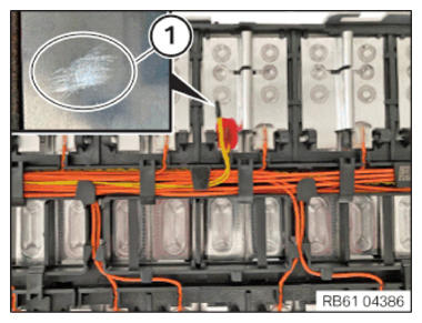
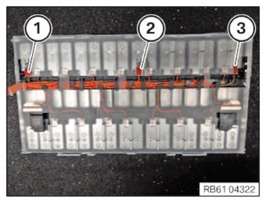
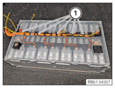
- Overview of the NTC sensors (1), (2), (3)
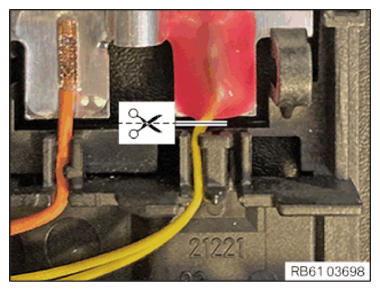
- Cut through all NTC lines with suitable tool (electronic side cutter) close to the adhesive area.
- Pull out the cut through lines from the cable duct.
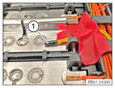
- Feed in the lines (1) and insert them in the cable duct.
NOTE:
To improve the presentation, the touch protection cover is not mounted in the subsequent steps.
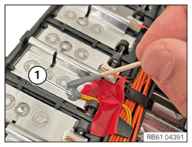
- Sand the adhesive area (1) with sandpaper with a grit of 700 to 1000.
- Then clean the area (1) with solvent cleaner R1.CONSUMABLE - CLEANING AGENT DESCRIPTION
Cleaning agent R1 100 ml, Bottle 83192211217 - Parts required for the repair:
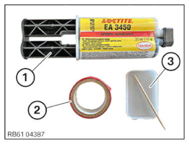
- (1) Adhesive 2K Loctite 3450
- Adhesive tape
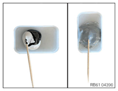
- Bowl for mixing the adhesive
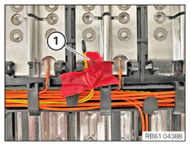
ADHESIVE DESCRIPTIONAdhesive 2K Loctite 3450 25 ml, Bottle 51252313730 CONSUMABLE - ADHESIVE DESCRIPTIONAdhesive tape 83192147666 - Position the NTC sensor lines and fix them with adhesive tape (1).
- Make sure that the NTC sensor is flush with the cell module. A gap is not permitted between the NTC sensor and the cell module.
- Squeeze the adhesive into the bowl and mix for 1 min. Before applying, let the adhesive rest for approx. 1 min.
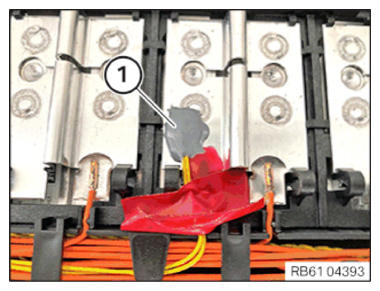
- Apply adhesive (1) and ensure that the NTC sensor and the lines are completely coated.
- While applying the adhesive (1), ensure that the NTC sensor is in contact with the cell module without any gaps.
- The adhesive (1) must have covered an area of at least three NTC sensor widths.
- Overview of the bonded NTC sensor (1).
- The insulating tape can be detached carefully 15 min after applying the adhesive (1). It must be ensured that the NTC sensor remains correctly positioned. After this waiting period, the following steps can be continued.
- After bonding, a photo must be taken for each NTC sensor on which the bonded connection is clearly visible. For documentation purposes, a TSARA case must be created with "Urgency Information". These photos must then be attached to the respective TSARA case.