Install the coolant return line for the exhaust turbocharger
NOTE:
TECHNICAL INFORMATION
Make sure that the connections are locked correctly. The locks must engage audibly.
Make sure that the connections are locked correctly. The locks must engage audibly.
- Using the special tool 0 496 714 (00 9 030)
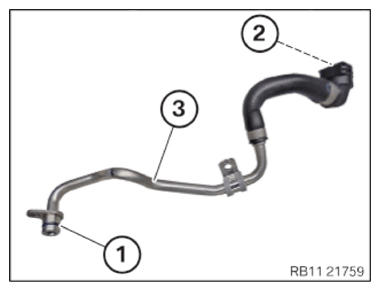
, replace the sealing rings (1) on the coolant return line (3).
Parts: Sealing rings
- Check the sealing rings (2) on the coolant return line (3) for damage; if necessary replace the coolant return line (3).
- Using the special tool 0 496 714 (00 9 030)
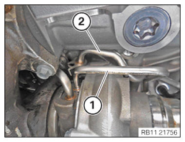
, replace the sealing ring (1) on the oil feed line (2) for the exhaust turbocharger.
Parts: Sealing ring
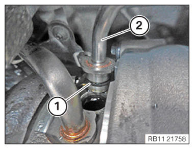
- Insert and position the coolant return line (2) for the exhaust turbocharger.
- Insert and install oil feed line (1) for the exhaust turbocharger.
- Feed in and install the coolant return line (2) for the exhaust turbocharger.
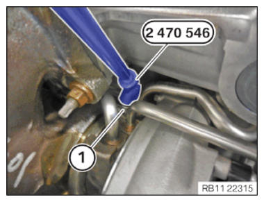
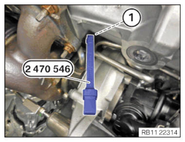
- Feed in screw (1) with special tool 2 470 546
and tighten hand-tight.
- Position special tool 2 470 546
on the screw (1).NOTE: TECHNICAL INFORMATION
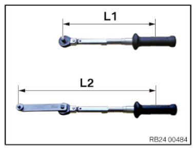
When using special tools that extend the lever arm of the torque wrench, the setpoint torque deviates from the adjustable torque.NOTE: Schematic diagram is for example purposes. Some parts may differ in certain details. - Converting the setpoint torque into the adjustable torque:
(setpoint torque x L1): L2 = adjustable torque
L1 = length from the center of the grip to the reversible ratchet head
L2 = length from the center of the handle to the engaging of the special tool in the bolt
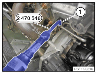
- Tighten screw (1) with the special tool 2 470 546
.TIGHTENING TORQUES SPECIFICATION
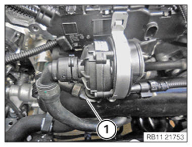
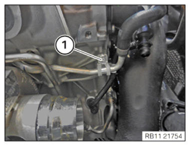
Coolant return line/oil feed line to exhaust turbocharger M6 x 12 tightening torque 8 Nm - Connect the coolant return line (1) for the exhaust turbocharger and lock.
- Make sure that the coolant return line (1) engages audibly.
- Tighten down screw (1).
TIGHTENING TORQUES SPECIFICATION
| Coolant return line holder to crankcase | ||
| M6X12 | tightening torque | 8 Nm |
Follow-up work
- Refer to INSTALLING BOTTOM CLEAN AIR PIPE .
- Refer to INSTALLING CLEAN AIR PIPE, TOP .
- Refer to INSTALLING THE INTAKE FILTER HOUSING (TENSION STRUT REMOVED ON SHOCK TOWER) .
- Refer to INSTALLING FAN COWL .
- Refer to INSTALLING THE REAR TOP CROSS CONNECTION .
- Refer to INSTALLING FRONT CROSS CONNECTION .
- Refer to INSTALLING BOTH FRONT-END STRUTS .
- Refer to INSTALLING THE COVER ON THE LEFT AND RIGHT IN THE ENGINE COMPARTMENT AT THE TOP .
- Refer to FILLING AND VENTING THE HIGH-TEMPERATURE COOLANT CIRCUIT .
- Refer to INSTALLING ACOUSTIC COVER .
- Refer to INSTALLING THE FRONT UNDERBODY PROTECTION OR FRONT THRUST FIELD .
- Refer to INSTALLING THE UNDERBODY PROTECTION OF THE STEERING GEAR OR THE FRONT THRUST FIELD .
- Refer to INSTALLING THE CENTER UNDERBODY PROTECTION .