Completely installing the prop shaft (plug-in - rear flexible disc)
NOTE:
RISK OF DAMAGE
Damage to the prop shaft during installation.
Non-observance of the installation guidelines for the prop shaft on the rear axle differential may cause severe damage.
Damage to the prop shaft during installation.
Non-observance of the installation guidelines for the prop shaft on the rear axle differential may cause severe damage.
- Always replace the recessed nut on the rear axle differential. Screw lock must be available.
- Strictly observe a minimum hardening time of three hours after having screwed in the recessed nut. The hardening time may be longer at lower temperatures.
- Observe following installation sequence:
- Position prop shaft - on transmission.
- Position the prop shaft at the rear axle differential.
- Position central mount.
- Observe the following screwing sequence:
- Recessed nut
- Flexible disc to transmission
- Central mount
NOTE:
TECHNICAL INFORMATION
For all-wheel drive vehicles from the 5 Series and 7 Series, the aluminum flexible discs have been eliminated and replaced with elastic flexible discs made of rubber as of production date 09/2015.
For all-wheel drive vehicles from the 5 Series and 7 Series, the aluminum flexible discs have been eliminated and replaced with elastic flexible discs made of rubber as of production date 09/2015.
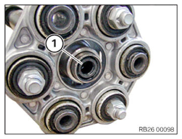
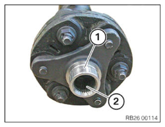
- Check the centering (1) for damage and replace if necessary.
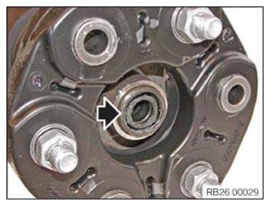
- Check the centering (arrow) for damage and replace if necessary.
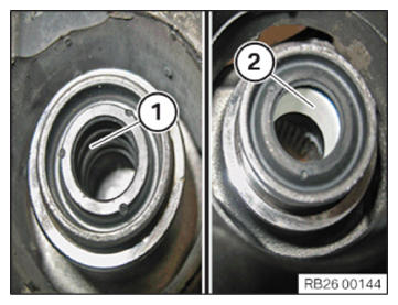
- Apply a thin coat of grease to the soft centering (1), if necessary.CONSUMABLE - LUBRICATING GREASE DESCRIPTION
Lubricating grease 100 g, 83 19 0 447 Olistamoly 2 LN 584 LO Tube 919 - Do not
grease the hard centering (2).
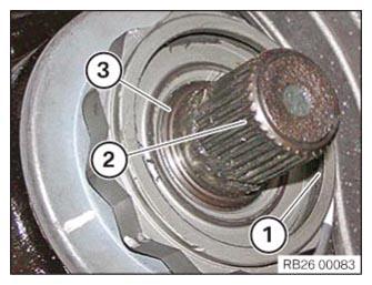
- Clean the recessed collar (1) of the twelve-edge flange nut and the gearing on the bevel drive pinion (2) of all residues and degrease.
- Top up the collar insert (1) with grease.CONSUMABLE - LUBRICATING GREASE DESCRIPTION
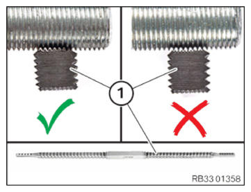
Lubricating grease 50 g, 83230417754 Optitemp HT 1 LF Tube - Use the thread file (1) to remove the adhesive residues from the thread.
- The correct thread pitch must be ensured!
NOTE:
RISK OF DAMAGE
Damage to the output flange.
Failure to observe the greasing specifications may lead to damage on the output flange.
Damage to the output flange.
Failure to observe the greasing specifications may lead to damage on the output flange.
- Do not contaminate the thread of the output flange with grease.
- Use the thread file to clean adhesive residue from the thread (1) of the flange.
- Clean gearing (2).
- Grease gearing (2).CONSUMABLE - LUBRICATING GREASE DESCRIPTION
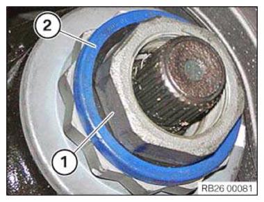
Lubricating grease 50 g, 83230417754 Optitemp HT 1 LF Tube - Replace the seal, recessed nut (1) and the retaining ring (2).
Parts: Seal, recessed nut, retaining ring
- Insert the recessed nut (1) with the seal into the recessed collar of the twelve-edge flange nut.
- Mount the retaining ring (2).
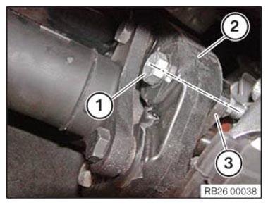
- It is imperative to reassemble the three-hole flange (3) with the flexible disc (2) in the same position to prevent the drivetrain from humming after reinstalling the prop shaft.
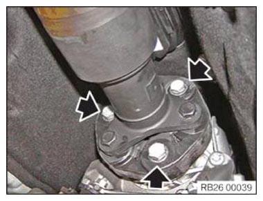
- Replace ZNS screws and self-locking nuts (1).
Parts: ZNS screws, self-locking nuts
- Position the screws and nuts (arrows).
- Tighten the screws.TIGHTENING TORQUES SPECIFICATION
Front flexible disc to prop shaft M12
Replace screws.
Jointing torque and angle rotation must be adhered to.
Tightening via screw.Joining torque
55 Nm
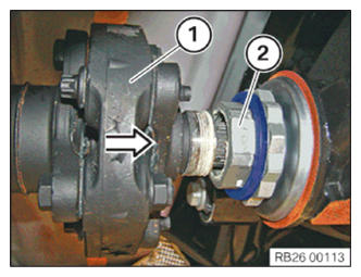
Angle of rotation 90° - Push the prop shaft (1) in arrow direction against the recessed nut (2) up to the stop.
- Unscrew the recessed nut (2) by at least 2 threads manually on the prop shaft (1) and fasten it.
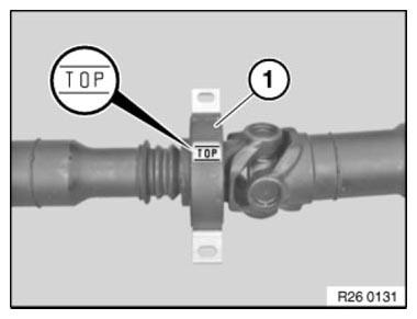
- Central mount with the TOP designation:
- Central mount (1) must be installed with the designation TOP at the top in the transmission tunnel.
- Position central mount.
- Position screws (1).
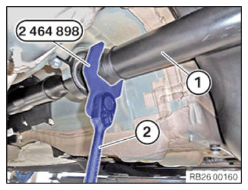
- Prop shafts with a narrow universal joint:
- With a special tool 2 464 898
and a suitable tool (2), secure the prop shaft (1) on the center universal joint from twisting.
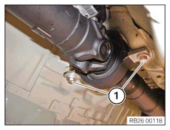
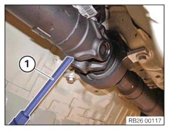
- Prop shafts with a wide universal joint:
- Secure the juncture shaft against twisting at the central universal joint using a suitable tool (1).NOTE: RISK OF DAMAGE
Damage to the flange nut.
Failure to observe the installation specifications may lead to serious damage to the flange nut and the rear axle differential.- Do not use the twelve-edge flange nut as counter support.
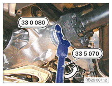
- Screw in the recessed nut within 5 minutes.
- Screw in the recessed nut counter-clockwise, see arrow direction with special tools 0 495 554 (33 5 070)
and 0 496 959 (33 0 080).
The recessed nut must be screwed into place within 5 min.
TIGHTENING TORQUES SPECIFICATIONPropeller shaft to rear axle differential Tightening torque Replace recessed nut. 100 Nm - After the propeller shaft is installed and the recessed nut is screwed in, strictly observe a hardening time of minimum 3 hours.
During this time the vehicle must not be moved or pushed!
- Hold down mounting bolts of the flexible disc on the nut and tighten via the screw.TIGHTENING TORQUES SPECIFICATION
Rear flexible disc to three-hole flange M12
Replace screws.
Joining torque and angle of rotation must be observed without fail.
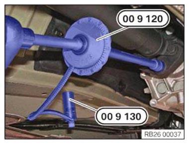
Tightening via screw.Joining torque 55 Nm Angle of rotation 90° - Secure the special tool angle of rotation 0 490 504 (00 9 120) with the magnet 0 495 108 (00 9 130) to the vehicle underbody and continue to screw it on as per the angle of rotation.
- Tighten down screws (1).TIGHTENING TORQUES SPECIFICATION
Central mount to body Tightening torque M8 19 Nm
Follow-up work
- Install transmission CROSS MEMBER .
- Install the HEAT SHIELDS .
- Install the complete EXHAUST SYSTEM .
- If installed: install the right, and on the left TORSION STRUT where required.
- Install the tunnel CONNECTING SUPPORTS .
- Install the transmission on the side UNDERBODY PLANKING .
- Install rear UNDERBODY PROTECTION .