Install the engine bridge
Risk of burning!
- Perform all work only on components that have cooled down.
Risk of scalding!
- Conduct all work in the vehicle wearing appropriate personal protective equipment only.
Risk of burning!
- Any work must exclusively be carried out with an exhaust system that has cooled down.
Preliminary work:
- Refer to DISCONNECTING ALL BATTERY GROUND LEADS .
- Refer to BRINGING FRONT COMPARTMENT LID IN THE SERVICE POSITION .
- Refer to REMOVING THE COVER IN THE ENGINE COMPARTMENT ON TOP .
- Refer to REMOVING THE TOP RIGHT COVER IN THE ENGINE COMPARTMENT .
- Refer to REMOVING THE COVER OF THE REAR RIGHT ENGINE COMPARTMENT .
- Refer to REMOVING THE COVER OF THE ENGINE COMPARTMENT AT THE REAR LEFT
- Refer to REMOVING THE ACOUSTIC COVER (2018-2019) or REMOVING THE ACOUSTIC COVER (2020-2022) .
- Refer to REMOVING THE COVER PANEL OF THE LEFT DME CONTROL UNIT .
- Refer to INSTALLING THE CONTROL UNIT BRACKET FOR CYLINDERS 5 TO 8 (2018-2019) or REMOVING THE CONTROL UNIT BRACKET FOR CYLINDERS 5 TO 8 (2020-2022) .
Prepared engine bridge
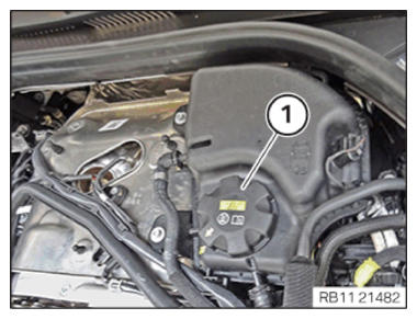
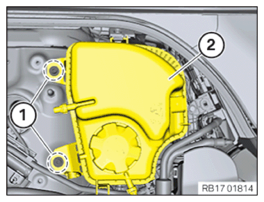
- Loosen the sealing cap (1) from the coolant expansion tank.
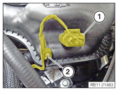
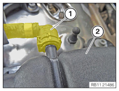
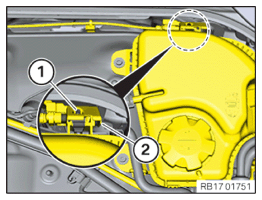
- Unlock plug connection (1) and disconnect.
- Unclip the wiring harness at the wiring harness mounting (2).
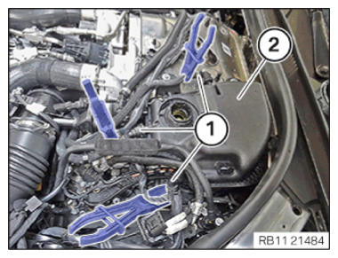
- Disconnecting the coolant hoses (1) from the coolant expansion tank (2) with standard clamping pliers.
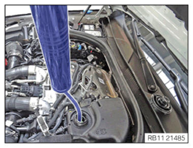
- Draw off the coolant with a standard syringe.
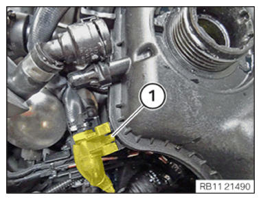
- Unlock and disconnect the coolant line (1) from the coolant expansion tank (2).
- Unlock and disconnect the coolant line (1) from the coolant expansion tank (2).
- Unlock and disconnect the coolant line (1) from the coolant expansion tank (2).
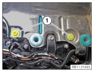
- Loosen screws (1).
- Unclip the coolant line from the bracket in the region (2).
- Version with a gasoline particulate filter:
Feed the cable (1) out of the brackets toward the front.
Remove the rear bonnet seal (2) from the guide toward the inside.
- Version with a gasoline particulate filter:
- Loosen screws (1).
- Carefully slide the coolant expansion tank (2) upwards and to the front.
- Version with a gasoline particulate filter:
Loosen screw (1).
Pull the holder of the gasoline particulate sensor (2) upwards and out of the guide.
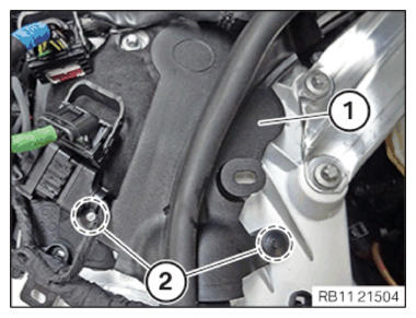
- Release the wiring harness mounting at the snap-in lug (1) and put it aside.
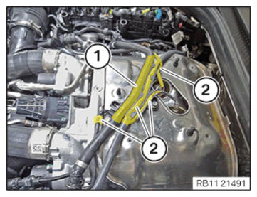
- Working upwards, unclip the engine ventilation line (1).
- Unclip the wiring harness from the attachments (2).
- Version with a gasoline particulate filter:
Release the screws (3).
Release the wiring harness mountings (2).
Set aside the holder (1) of the gasoline particulate sensor.
- Version with a gasoline particulate filter:
Loosen screw (1).
Slide the holder of the gasoline particulate sensor (2) with the gasoline particulate sensor (2) towards the rear.
- Version with a gasoline particulate filter:
Unclip cable (1) of the Lambda oxygen sensor from the holder.
Unclip wiring harness (2).
Unclip intake line (3).
Unclip the cable of the Lambda oxygen sensor from the bracket (4).
- Loosen screws (1).
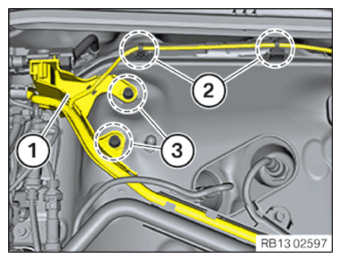
- Unclip the transmission wiring harness from the bracket (1).
- Unclip the plug connector (2) upwards from the heat shield.
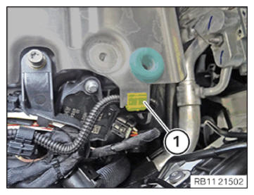
- Unclip the cable of the Lambda oxygen sensor from the bracket (1).
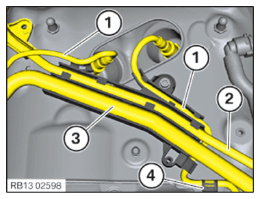
- Unlock and disconnect the engine ventilation line from the retaining clip in the region of (1).
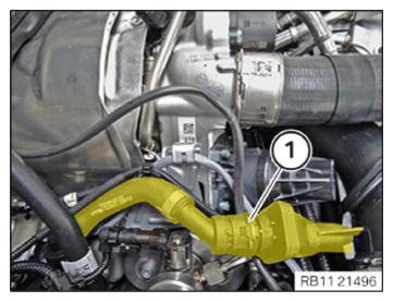
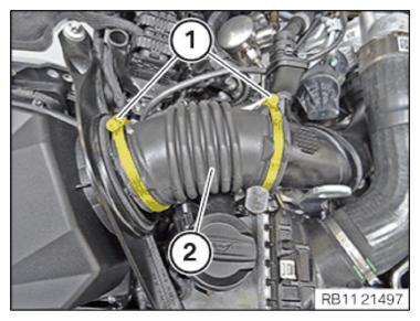
- Release the hose clamps (1).
- Remove the bellows (2).
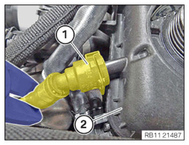
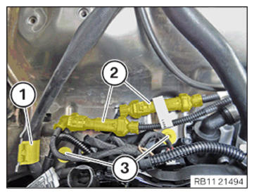
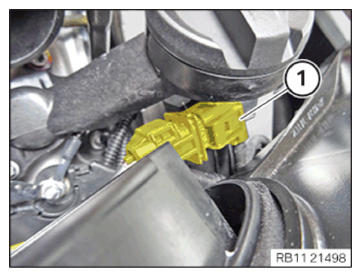
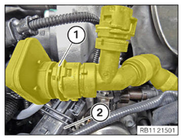
- Unlock plug connection (1) and disconnect.
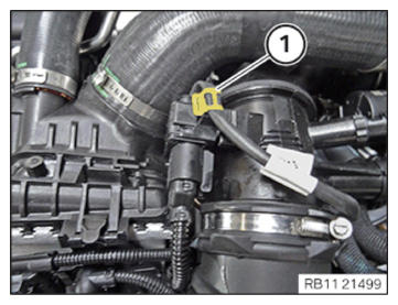
- Unclip the cable of the Lambda oxygen sensor from the bracket (1).
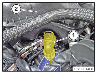
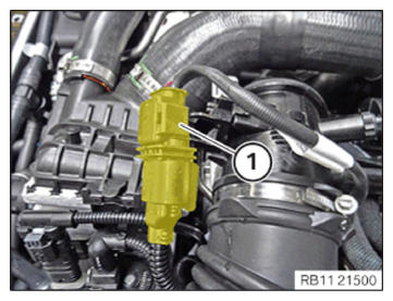
- Unlock plug connection (1) and disconnect.
- Unlock and disconnect the engine ventilation line from the retaining clip in the region of (1).
- Feed the connector (2) of the Lambda oxygen sensor through.
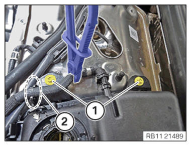
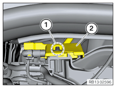
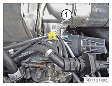
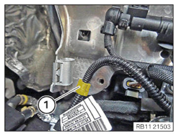
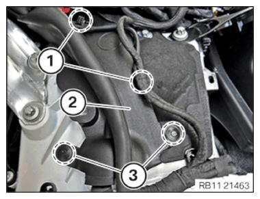
- Unclip the wiring harness mounting (1) at the heat shield.
- Unclip the wiring harness mounting (1) at the heat shield.
- Lift out heat shield.
- Remove the expanding rivet (1).
- Remove clips (2).
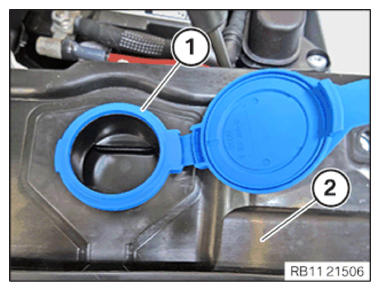
- Remove lid (1) of the washer fluid reservoir to the top.
- Remove seal (2) of the side panel.
- Remove the expanding rivet (1).
- Remove clips (2).
- Remove Bowden cables (3) from the side panel seal.
- Remove the side panel seal.
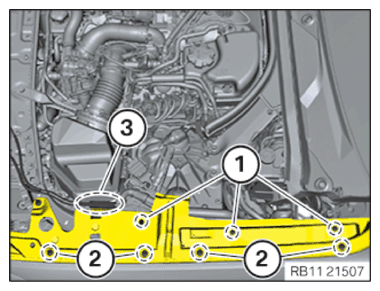
- Release the expanding rivet (2).
- Remove the hood seal on the side (1).
- Release the wiring harness mountings (1).
- Release the expanding rivet (3).
- Remove the hood seal on the side (2).
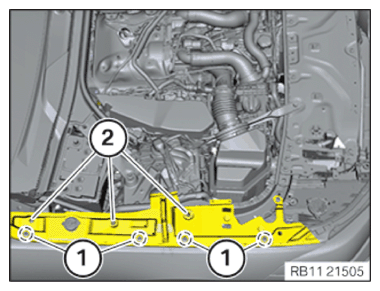
- Release the screws in areas (1).
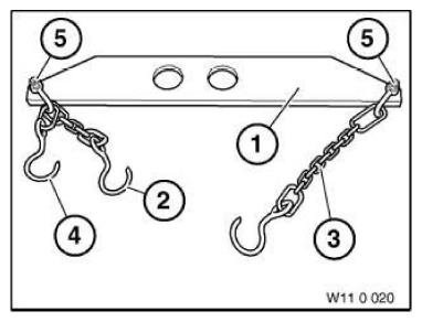
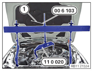
- Prepare special tool 0 490 567 (11 0 020).
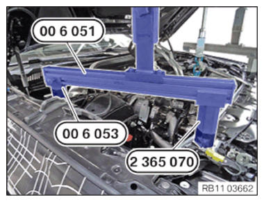
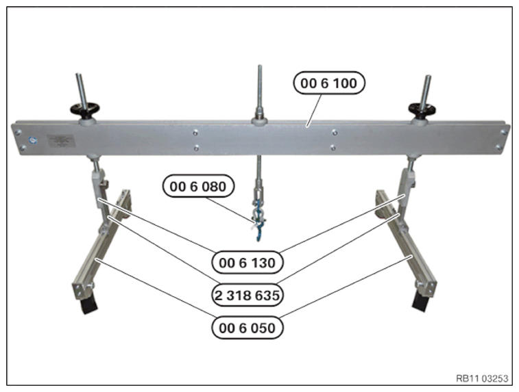
- Mount special tools 2 365 070
and 0 496 438 (00 6 053)
on profile strips 0 496 436 (00 6 051). NOTE: Description is for left component only. Procedure on the right side is identical.
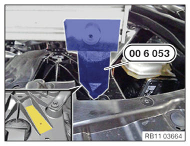
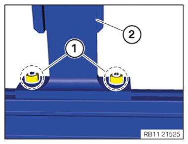
- Position the special tool 0 496 438 (00 6 053)
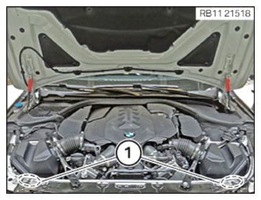
on the shock towers as shown.NOTE: Description is for left component only. Procedure on the right side is identical.
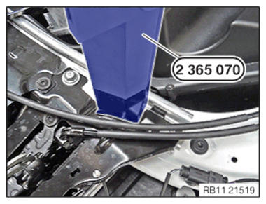
- Position the special tool 2 365 070
on the lock support as shown.NOTE: Conduct the following operation with the assistance of a second person.
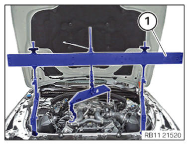
- Carefully position engine bridge (1) with the special tool 0 490 567 (11 0 020)
with help from an assistant.
- If necessary, release the nuts (1) and position the engine bridge (2).
Remove the front left and right wheels
Further information is available.
NOTE: Perform the steps on the left and right side.Removing the wheel
Further information is available.
NOTE: A wheel lifter is recommended for easier wheel removal and installation without exertion. - In vehicles with M Carbon ceramic brake: It is essential to use the wheel lifter to remove the wheel.
This process is intended to prevent damage to the brake disc.
- If several wheels are removed simultaneously: Use a piece of chalk to mark on each tire the axle and side on which the corresponding wheel is fitted.
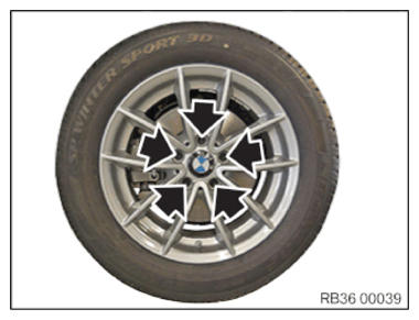
- Release the lug bolts (arrows) crosswise and remove the wheel.
- For releasing and tightening lug bolts with the security code: Use the correct adapter from the set of special tools 0 492 518 (36 1 300).
Remove the cover of the steering assembly on the left and right
NOTE: Description is for left component only. Procedure on the right side is identical.Remove the cover of the steering assembly
Further information is available.
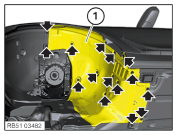
NOTE: To provide a better overview: Schematic diagram with partially hidden components. - Release all bolts (arrows).
- Remove cover (1).
Remove the rear section of the wheel arch cover on the front left and right
NOTE: Description is for left component only. Procedure on the right side is identical.Remove the rear section of the front wheel arch cover front
Further information is available.
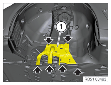
NOTE: To provide a better overview: Schematic diagram with partially hidden components. - Remove screws (arrows).
- Guide the wheel arch cover (1) out.
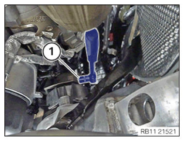
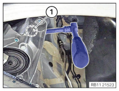
- Release screw (1) of the right engine mount with standard tool.
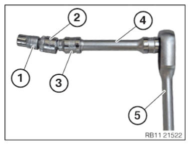
- Prepare tools:
- Torx socket E12
- Reduce from 1/2 inch to 3/8 inch
- Groove 12.5°
- Short extension of 1/2 inch
- 1/2" reversible ratchet
- Release the screw (1) of the left engine mount with the prepared tool.
- Lift the engine by 10 mm by turning the special tool 2 361 506 (00 6 103) (1) with the special tool 0 490 567 (11 0 020).