Removing the intake plenum
NOTE:
TECHNICAL INFORMATION
Additional coolant can leakage. Make sure that no coolant enters the intake port of the cylinder head.
Additional coolant can leakage. Make sure that no coolant enters the intake port of the cylinder head.
NOTE:
TECHNICAL INFORMATION
Collect and dispose of emerging fluids. Observe country-specific waste disposal regulations.
Collect and dispose of emerging fluids. Observe country-specific waste disposal regulations.
Preliminary work
- Refer to DISCONNECTING ALL BATTERY GROUND LEADS .
- Refer to BRINGING FRONT COMPARTMENT LID IN THE SERVICE POSITION .
- Refer to REMOVING THE ACOUSTIC COVER .
- Refer to REMOVING THE SEAL FOR THE HOOD REAR .
- Refer to REMOVING ACOUSTIC COVER AT REAR .
- Refer to REMOVING THE DME CONTROL UNIT (540i 2017-2020) , or REMOVING THE DME CONTROL UNIT (540i 2021-2022, 540i xDrive 2021-2022) .
- Refer to REMOVING THE INTEGRATED POWER SUPPLY MODULE (PDM) (540i 2017-2020) , or REMOVING THE INTEGRATED POWER SUPPLY MODULE (PDM) (540i 2021-2022, 540i xDrive 2021-2022) .
- Refer to REMOVING CONTROL UNIT BRACKET (540i 2017-2020) , or REMOVING THE CONTROL UNIT HOLDER (540i 2021-2022\, 540i xDrive 2021-2022) .
- Refer to REMOVING THE COVER ON LEFT AND RIGHT IN THE ENGINE COMPARTMENT AT THE TOP .
- Refer to REMOVING BOTH FRONT-END STRUTS .
- Refer to REMOVING FRONT CROSS CONNECTION .
- Refer to REMOVING THE REAR TOP CROSS CONNECTION .
- Refer to REMOVING THE FAN COWL .
- Refer to REMOVING THE FRONT UNDERBODY PROTECTION OR FRONT THRUST FIELD .
- Refer to REMOVING THE UNDERBODY PROTECTION OF THE STEERING GEAR AND THRUST FIELD RESPECTIVELY .
- Refer to DRAINING THE COOLANT FROM THE LOW-TEMPERATURE COOLING SYSTEM .
- Refer to CONNECTING THE COOLANT LINES FOR THE LOW-TEMPERATURE COOLANT CIRCUIT .
- Refer to REMOVING TANK VENT VALVE .
NOTE:
RISK OF DAMAGE
Damage to wires when disconnecting connectors and plug connections.
Sheared wires can cause a short circuit.
Damage to wires when disconnecting connectors and plug connections.
Sheared wires can cause a short circuit.
- Do not pull on wires when disconnecting connectors and plug connections.
NOTE:
TECHNICAL INFORMATION
Additional coolant can leakage. Make sure that no coolant enters the intake port of the cylinder head.
Additional coolant can leakage. Make sure that no coolant enters the intake port of the cylinder head.
NOTE:
TECHNICAL INFORMATION
Collect and dispose of emerging fluids. Observe country-specific waste disposal regulations.
Collect and dispose of emerging fluids. Observe country-specific waste disposal regulations.
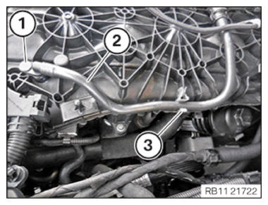
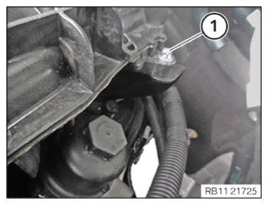
- Loosen screw (1).
- Guide tank ventilation line (2) out of clamp (3) and remove it.
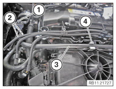
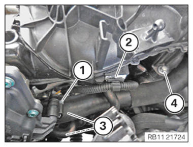
- Unlock and release the plug connections (1).
- Unlock the locks (2).
- Guide tank ventilation line (3) out of clamp (4) and remove it.
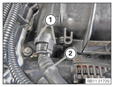
- Unlock the locks (1).
- Feed the tank ventilation line (2) out and set it aside.
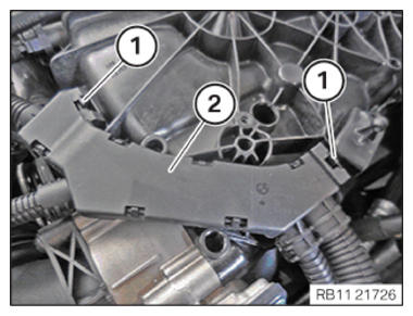
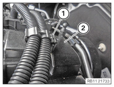
- Unlock the locks (1).
- Feed out the wiring harness section (2) for the sensor system 2
and set it aside.
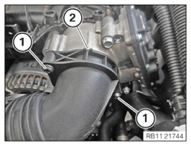
- Loosen screws (1).
- Feed out charge air line (2) and place to one side.
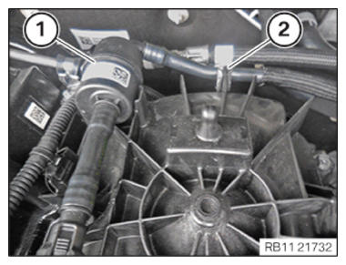
- Unlock and release plug connection (1).
- Loosen clamp (2).
- Thread off coolant line (3) and place to the side.
- Loosen screw (4).
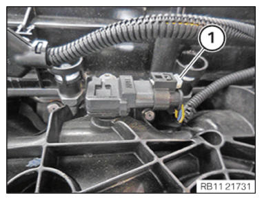
- Unlock and release plug connection (1).
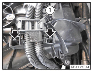
- Unlock the locks (arrows).
- Feed out the wiring harness section (1) for the injectors and ignition coils and put to one side.
- Guide tank ventilation line (1) out of clamp (2) and place it aside.
- Feed out the wiring harness section (1) for the injectors and ignition coils of the cylinder head cover (2) and put to one side.
- Loosen screw (1).
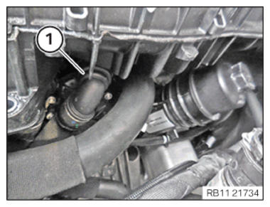
- Unlock and loosen coolant line (1).
- Catch and dispose of escaping coolant.
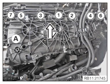
- Loosen screws in the order (7) to (1).
- Slightly lift intake plenum (A) in arrow direction
.
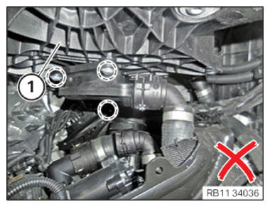
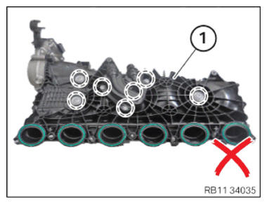
NOTE: TECHNICAL INFORMATION
The tension rod screws and mounting bolts from the connecting neck on the intake plenum are not allowed to be opened. - Do not
release screws in the marked area
on the intake plenum (1).NOTE: TECHNICAL INFORMATION
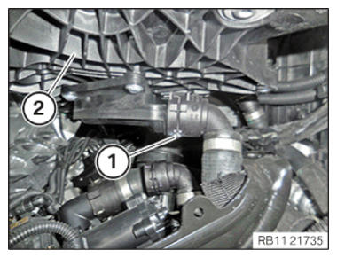
Additional coolant can leakage. Make sure that no coolant enters the intake port of the cylinder head. - Unlock and release the coolant line (1) under the intake plenum (2).
- Catch and dispose of escaping coolant.
- Feed out the intake plenum (2) and remove it.
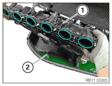
- Empty the remaining coolant (2) from the intake plenum (1).NOTE: TECHNICAL INFORMATION
The tension rod screws and mounting bolts from the connecting neck on the intake plenum are not allowed to be opened. - Do not release screws in the marked area on the intake plenum (1).