Checking the position of the intake camshaft (540i 2017-2022, 540i xDrive 2017-2022)
WARNING:
Hot fluids.
Risk of scalding!
Risk of scalding!
- Conduct all work in the vehicle wearing appropriate personal protective equipment only.
WARNING:
Hot surfaces.
Risk of burning!
Risk of burning!
- Perform all work only on components that have cooled down.
WARNING:
Working on fuel system.
Risk of fire! Danger of explosion!
Risk of fire! Danger of explosion!
- When working on the fuel system, make sure the workstation has sufficient ventilation, e.g., by means of extraction.
- Tightly seal off open lines and connections; collect any leakage fuel directly at the point of exit.
- No fire, sparks, open flames or smoking.
CAUTION:
On releasing high pressure line, fuel may emerge at high speed.
Injury hazard!
Injury hazard!
- Wear suitable personal protective equipment.
- Before performing any installation work, allow cooling system to cool down to less than 40°C.
- Note warnings on cylinder head cover.
NOTE:
Collect and dispose of emerging fluids. Observe country-specific waste disposal regulations.
Preliminary work
- Refer to DISCONNECTING ALL BATTERY GROUND LEADS .
- Refer to REMOVING THE ACOUSTIC COVER .
- Refer to REMOVING INTAKE SILENCER HOUSING .
- Refer to REMOVING THE RESONATOR WITH THE TOP CLEAN AIR PIPE .
- Refer to REMOVING THE COVER ON LEFT AND RIGHT IN THE ENGINE COMPARTMENT AT THE TOP .
- Refer to REMOVING THE LEFT AND RIGHT FRONT-END STRUT .
- Refer to REMOVING FRONT CROSS CONNECTION .
- Refer to REMOVING THE REAR TOP CROSS CONNECTION .
- Refer to REMOVING THE FAN COWL .
- Refer to REMOVING THE SEAL FOR THE HOOD REAR .
- Refer to REMOVING ACOUSTIC COVER AT REAR .
- Refer to REMOVING THE COVER OF THE ENGINE COMPARTMENT AT THE REAR LEFT .
- Refer to REMOVING LEFT AND RIGHT WIPER ARM .
- Refer to REMOVING THE COVER OF THE REAR RIGHT ENGINE COMPARTMENT .
- Refer to REMOVING TRAILING LINK AT SPRING BOLT .
- Refer to REMOVING THE COWL UPPER PART IN THE CENTER .
- Refer to REMOVING THE FRONT UNDERBODY PROTECTION OR FRONT THRUST FIELD .
- Refer to REMOVING THE FRONT THRUST FIELD .
- Refer to DETACHING THE CHARGE AIR LINE FROM THE THROTTLE BODY .
- Refer to REMOVING TANK VENT VALVE .
- Refer to REMOVING THE DME CONTROL UNIT .
- Refer to REMOVING CONTROL UNIT BRACKET .
- Refer to DRAINING THE COOLANT FROM THE LOW-TEMPERATURE COOLING SYSTEM .
- Refer to REMOVING THE INTAKE PLENUM .
- Refer to REMOVING THE SEALING FRAME ON LEFT AND RIGHT .
- Refer to REMOVING THE CENTER BULKHEAD LOWER PART .
- Refer to REMOVING BOTH ACTUATORS .
- Refer to REMOVING FRONT ENGINE ENCAPSULATION .
- Refer to REMOVING IGNITION COILS .
- Refer to REMOVING THE HIGH PRESSURE LINE BETWEEN THE RAIL AND THE HIGH PRESSURE PUMP .
- Refer to REMOVING HIGH PRESSURE PUMP .
- Refer to REMOVING THE INJECTORS FOR CYLINDERS 1 TO 3 .
- Refer to REMOVING THE INJECTORS FOR CYLINDERS 4 TO 6 .
- Refer to REMOVING THE CYLINDER HEAD COVER .
- Refer to ADJUSTING THE ECCENTRIC SHAFT TO MINIMUM LIFT .
Check
- Check position of the intake camshaft on the respective cylinders.
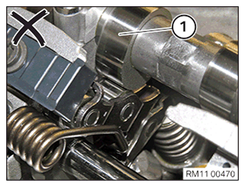
Result
» Cam (1) of the intake camshaft runs on the intermediate lever.
Measure
- Continue to turn the engine at the vibration damper with the special tool 0 493 380 (11 6 480) in the direction of engine rotation.