Remove exhaust camshaft
WARNING:
Working on 12 V electrical system.
Risk of short circuits! Risk of fire!
Risk of short circuits! Risk of fire!
- Make sure that there is no charger connected to the jump start terminal in the engine compartment.
- Detach battery ground lead from battery.
- For auxiliary batteries: Detach battery minus cables from all auxiliary batteries.
WARNING:
Working on fuel system.
Risk of fire! Danger of explosion!
Risk of fire! Danger of explosion!
- When working on the fuel system, make sure the workstation has sufficient ventilation, e.g., by means of extraction.
- Tightly seal off open lines and connections; collect any leakage fuel directly at the point of exit.
- No fire, sparks, open flames or smoking.
CAUTION:
On releasing high pressure line, fuel may emerge at high speed.
Injury hazard!
Injury hazard!
- Wear suitable personal protective equipment.
- Before performing any installation work, allow cooling system to cool down to less than 40°C.
- Note warnings on cylinder head cover.
NOTE:
RISK OF DAMAGE
Damage to battery terminal, the safety battery terminal or the intelligent battery sensor (IBS).
Damaged battery terminals can lead to malfunctions or vehicle electrical system faults.
Damage to battery terminal, the safety battery terminal or the intelligent battery sensor (IBS).
Damaged battery terminals can lead to malfunctions or vehicle electrical system faults.
- Detach battery terminal from battery pole by carefully shifting to and fro. Do not pry off using a tool.
NOTE:
TECHNICAL INFORMATION
Collect and dispose of emerging fluids. Observe country-specific waste disposal regulations.
Collect and dispose of emerging fluids. Observe country-specific waste disposal regulations.
NOTE:
TECHNICAL INFORMATION
After replacing one or more VANOS central valves or VANOS adjusters:
When removing, make note of the identification/part number of the VANOS central valve or VANOS adjuster and consider writing it down.
It must be replaced with a VANOS adjuster or VANOS central valve with the same part number. A mixed installation is not allowed.
Read out the vehicle I-level and proceed accordingly.
Be absolutely certain to pay attention to PuMA measure 64122020.
For further information, see the applicable BMW parts catalogue.
Preliminary work
- Refer to DISCONNECTING ALL BATTERY GROUND LEADS .
- Refer to REMOVING THE COVER OF THE ENGINE COMPARTMENT AT THE REAR LEFT .
- Refer to BRINGING FRONT COMPARTMENT LID IN THE SERVICE POSITION .
- Refer to REMOVING THE SEAL FOR THE HOOD REAR .
- Refer to REMOVING THE ACOUSTIC COVER .
- Refer to REMOVING LEFT AND RIGHT WIPER ARM .
- Refer to REMOVING THE COWL COVER .
- Refer to REMOVING TRAILING LINK AT SPRING BOLT .
- Refer to REMOVING THE COWL UPPER PART IN THE CENTER .
- Refer to REMOVING ACOUSTIC COVER AT REAR .
- Refer to REMOVING THE SEALING FRAME ON LEFT AND RIGHT .
- Refer to REMOVING THE CENTER BULKHEAD LOWER PART .
- Refer to REMOVING BOTH ACTUATORS .
- Refer to REMOVING IGNITION COILS .
- Refer to REPLACING SPARK PLUGS .
- Refer to REMOVING FUEL DELIVERY LINE .
- Refer to REMOVING THE HIGH PRESSURE LINE BETWEEN THE RAIL AND THE HIGH PRESSURE PUMP .
- Refer to REMOVING HIGH PRESSURE PUMP .
- Refer to REMOVING THE INJECTORS FOR CYLINDERS 1 TO 3 .
- Refer to REMOVING THE INJECTORS FOR CYLINDERS 4 TO 6 .
- Refer to REMOVING THE COVER ON LEFT AND RIGHT IN THE ENGINE COMPARTMENT AT THE TOP .
- Refer to REMOVING THE LEFT AND RIGHT FRONT-END STRUT .
- Refer to REMOVING FRONT CROSS CONNECTION .
- Refer to REMOVING THE REAR TOP CROSS CONNECTION .
- Refer to REMOVING THE FAN COWL .
- Refer to REMOVING INTAKE SILENCER HOUSING .
- Refer to REMOVING THE RESONATOR WITH THE TOP CLEAN AIR PIPE .
- Refer to REMOVING FRONT ENGINE ENCAPSULATION .
- Refer to REMOVING THE FRONT UNDERBODY PROTECTION OR FRONT THRUST FIELD .
- Refer to REMOVING THE STIFFENING PLATE .
- Refer to REMOVING STARTER MOTOR .
- Refer to REMOVING THE CYLINDER HEAD COVER .
- Refer to TURNING THE ENGINE ON THE VIBRATION DAMPER .
- Refer to BLOCKING THE CRANKSHAFT IN THE TDC FIRING POSITION OF THE FIRST CYLINDER (AUTOMATIC TRANSMISSION) .
- Refer to BLOCKING THE CAMSHAFTS .
- Refer to REMOVING CHAIN TENSIONER .
- Refer to RELEASING THE VANOS CENTRAL VALVE .
- Refer to REMOVING EXHAUST CAMSHAFT ADJUSTER .
- Refer to DISASSEMBLING THE SPECIAL TOOL 2 358 122 .
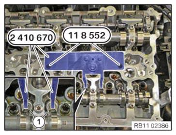
- Position the special tool 2 410 670 at cylinder 2 and hand-tighten it with the special tool 0 495 741 (11 8 552) from the set of special tools 0 495 739 (11 8 550).
- Screw in both roller cam followers (1) on 2nd cylinder with the spindle nut of the special tool 2 410 670
up to the limit position.
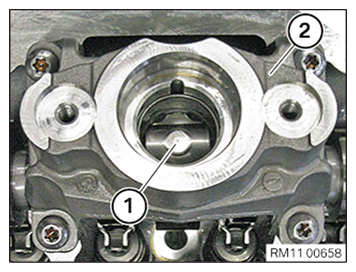
- Remove the roller tappet (1) from high pressure pump bracket (2).
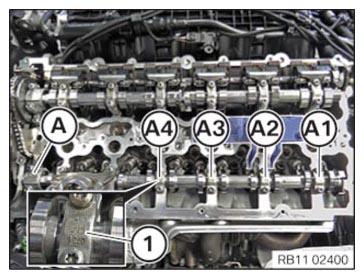
- Pay attention to the numbering on the exhaust camshaft bearing cap.
The exhaust camshaft bearing caps are numbered from (A1) till (A4).
The exhaust camshaft bearing cap (A) is a thrust bearing.
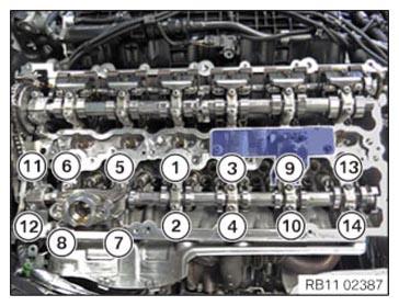
- Release screws in the right sequence (14) till (1) in semi circle pattern.
- Remove high pressure pump bracket and all exhaust camshaft bearing cap.
- Place all exhaust camshaft bearing cap in order in special tool 0 495 105 (11 4 480).
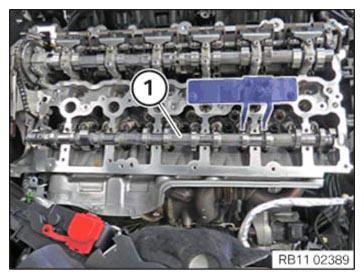
- (1) Remove exhaust camshaft in upward direction.